MECHANICAL TECHNOLOGY Past Paper FEBRUARY/MARCH 2016 Memo/Memorandum - GRADE 12 NATIONAL SENIOR CERTIFICATE
Share via Whatsapp Join our WhatsApp Group Join our Telegram GroupMECHANICAL TECHNOLOGY
FEBRUARY/MARCH 2016
MEMORANDUM
MARKS: 200
TIME: 3 hours
QUESTION 1: MULTIPLE-CHOICE QUESTIONS
1.1 C √ (1)
1.2 B √ (1)
1.3 D √ (1)
1.4 D √ (1)
1.5 A √ (1)
1.6 C √ (1)
1.7 D √ (1)
1.8 D √ (1)
1.9 B √ (1)
1.10 D √ (1)
1.11 D √ (1)
1.12 C √ (1)
1.13 B √ (1)
1.14 B √ (1)
1.15 A √ (1)
1.16 C √ (1)
1.17 A √ (1)
1.18 C √ (1)
1.19 D √ (1)
1.20 B √ (1)
[20]
QUESTION 2: SAFETY
2.1 Safety – Centre lathe
- Look out for revolving work pieces √
- Do not remove shavings by hand √
- Be careful not to run the cutting tool into the chuck √
- Do not make any adjustments on the work piece while the machine is running √
- Do not leave tools on the machine while in operation √ (Any 2 x 1) (2)
2.2 Safety – Tensile Tester
- Use safety goggles √
- Do not apply excessive pressure √
- Test piece to be well secured for testing √
- Check hydraulic fluid level √ (Any 2 x 1) (2)
2.3 Safety – Spring Tester
- Spring tester should be in a good condition √
- Spring tester must be fitted correctly and firmly √
- Ensure that the spring cannot slip out of position before applying the load √
- An uniform load must be applied √
- Release the load carefully and uniformly √ (Any 2 x 1) (2)
2.4 Safety – Cylinder Leakage
- Clean the area around the spark plug, before removing the spark plug √
- To prevent dirt from falling into the cylinder. √
- Be careful when removing radiator cap √
- The water may be hot and under pressure. √
- Do not exceed the specified pressure to test the cylinder √
- To prevent damage to the seals and tester. √
- The tester must fit properly and be well tightened in the spark hole or injector hole √
- To prevent damage to the tester and spark hole or injector hole. √
Any 2 x 2 (4)
- To prevent damage to the tester and spark hole or injector hole. √
[10]
QUESTION 3: TOOLS AND EQUIPMENT
3.1 Compression testing
3.1.1
- Wet compression test √
- Dry compression test √ (2)
3.1.2
- Worn cylinders √
- Worn piston rings √
- Worn piston √
- Leaking inlet valve √
- Leaking exhaust valve √
- Leaking cylinder head gasket √ (Any 2 x 1) (2)
3.2 Oil pump
- Oil pressure meter or oil pressure tester √ (1)
3.3 Cooling system test
- Remove the radiator cap and fit the tester √
- Pump air at the prescribed pressure into the system √
- Note the reading √ and if the reading drops, it indicates a leaking system √
- To test for a leaking cylinder-head gasket, √ the engine is started. √
- If the reading increases while the engine idles, it indicates on a leaking cylinder-head gasket √ (7) [12]
QUESTION 4: MATERIALS
4.1 Iron-carbon properties
4.1.1 Pearlite:
- Good ductility √
- Hard √
- Strong and tough √
- Resistant to deformation √ (Any 2 x 1) (2)
4.1.2 Cementite:
- Intensely hard √
- Brittle. √ (2)
4.2 Critical points
4.2.1 AC1 – lower critical point
- The lowest temperature to which steel must be heated to be hardened. √√
- The lowest temperature where the structure starts to change. √√ (Any 1 x 2) (2)
4.2.2 AC3 – high critical point
- The highest temperature to which the steel can be heated to obtain maximum hardness. √√
- The temperature where the steel completely loses its magnetic properties. √√
- The temperature where the steel's structure is at its finest. √√ (Any 1 x 2) (2)
4.3 Carbon content determines the hardness of steel. √ (1)
4.4 Cementite structure in steel determines the hardness. √ (1)
4.5 Ferrite structure in steel determines the ductility. √ (1)
4.6
Austenite is a solid solution of iron and carbon also called iron carbide. √ The structure is at its finest. √ (2)
[13]
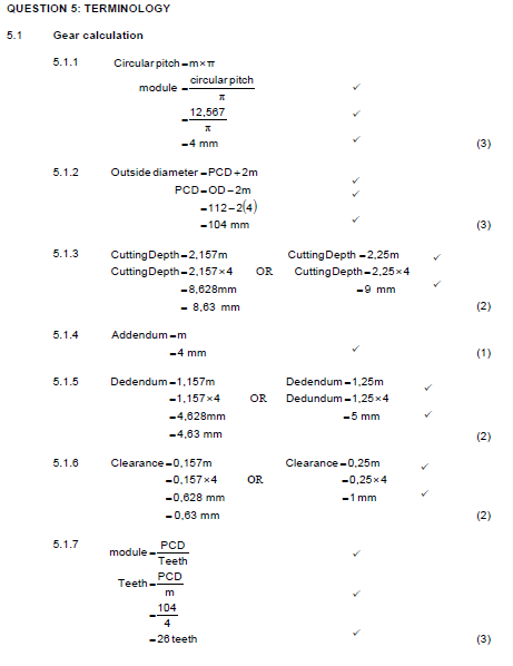
QUESTION 5: TERMINOLOGY
5.1 Gear calculation
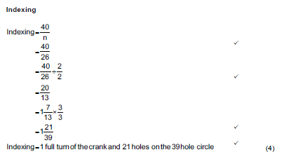
5.2
5.3 Screw thread cutting
- Set up the work piece in the lathe and turn the part to be threaded to the major diameter of the thread. √
- Set the compound slide to the correct angle (30°) to the right and set the tool up accurately in the post. √
- Consult the index plate of the quick-change gearbox for 2 mm pitch and move the levers accordingly. √
- Start the lathe and set the cutting tool so that it just touches the work piece. Set graduated dials to zero (cross feed and compound slide) √
- Move cutting tool a short distance off end of work piece and feed compound slide say 0,06 mm inwards. √
- With lathe turning, engage half nuts at the correct line on the chasing dial, putting the first cut in progress. √
- Withdraw the cutting tool quickly and disengage the half-nut lever. Return the carriage to the starting point of the thread. √ OR Stop the machine, leave half nut engaged, back off slide past zero and return carriage to start position in reverse √
- Check with thread gauge to see if thread pitch is correct. √
- Repeat with successive cuts until thread is complete. (Remember to bring cross-feed collar back to zero for each cut) √
- Each successive cut is set by means of the compound slide. Check thread with ring gauge for correct fit. √
(10)
[30]
QUESTION 6: JOINING METHODS
6.1 MIG/MAGS welding equipment
6.1.1 MIG/MAGS welding equipment √ (1)
6.1.2 Labels
A = Shielding gas cylinder √
B = Regulator √
C = Gas flow meter √
D = Continuous wire reel √
E = Welding gun √
F = Arc √
G = Earth clamp √ (7)
6.1.3 Purpose
Prevents oxygen √ to come in contact with the molten metal.√ (2)
6.2 Weld defects
6.2.1 Defect: Slag inclusion
Causes:
- Included angle is too narrow. √
- Rapid chilling. √
- Weld temperature is too low. √
- High viscosity of molten metal. √
- Slag from previous run weld not removed. √ (Any 2 x 1) (2)
6.2.2 Defect: Undercutting
Causes:
- Faulty electrode manipulation. √
- Current too high. √
- Arc length too long. √
- Speed of weld too fast. √ (Any 2 x 1) (2)
6.3 Welding defects
6.3.1
Defect: Lack of fusion
Preventions:
- Adjust the electrode angle and prepare the V groove properly.√
- Weave must be sufficient to melt sides of the joint. √
- Proper current will allow fusion. √
- Adjust welding speed to ensure fusion. √ (Any 2 x 1) (2)
6.3.2 Defect: Weld craters
Preventions:
- Use lower current. √
- Use proper welding technique. √
- Use correct electrode √ (Any 2 x 1) (2)
6.4 Dye penetration test
- Clean the weld that needs to be tested. √
- The dye is sprayed onto the clean surface. √
- Allow the dye to penetrate the weld joint. √
- Excess dye is cleaned away with a cleaning agent. √
- Allow surface to dry thoroughly. √
- Spray a developer onto the surface to bring out the dye trapped in the crack. √
- The dye will show all the surface defects√ (7)
[25]
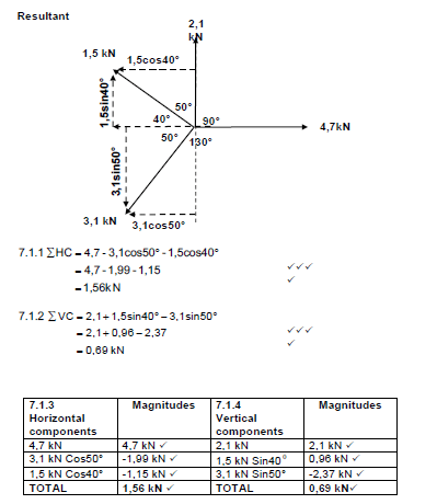
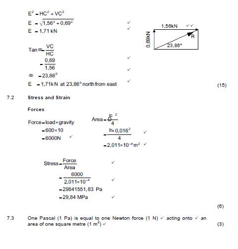
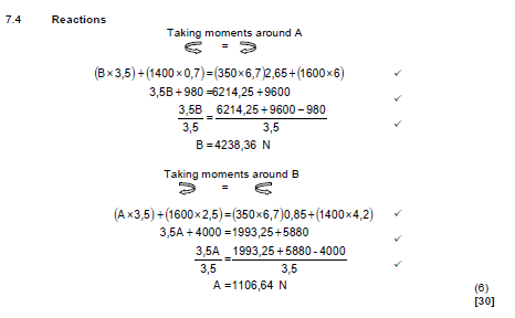
QUESTION 7: FORCES
7.1 Resultant
QUESTION 8: MAINTENANCE
8.1 Routine maintenance.
- Tear on the belt.√
- Misalignment of belt drive. √
- Overheating of components. √
- Belt slip. √
- Belt wear. √
- Pulley wear. √
- Financial loss due to the damage suffered.√
- Loss of valuable production time. √ (Any 2 x 1) (2)
8.2 Cutting fluid
- To allow it to flow easily √
- Dissipate excess heat √
- Prevent excessive load on pump √ (Any 2 x 1) (2)
8.3 Flash point
Is the lowest temperature at which the oil gives off a vapour which will ignite. √√ (2)
8.4
'API'
American Petroleum Institute √√ (2)
8.5 Automatic transmission fluid
- Transmit power in the torque convertor √
- Let hydraulic fluid transmit energy in order to move various parts such as the servo unit. √
- Acts as heat transfer medium to transfer heat within the transmission to outside and assist in cooling it down. √
- Acts as a lubricant for gears and bearings. √(Any 2 x 1) (2)
8.6 Replace belt in a drill press
- Machine should be switched off the locked out. √
- Tension on the belt to be released by loosening an adjusting screw or releasing the belt tensioner. √
- Remove the belt. √
- Replace with new belt of the correct type and size. √
- The belt should be re-tensioned and aligned. √ (5)
[15]
QUESTION 9: SYSTEMS AND CONTROL
9.1 Gear drive
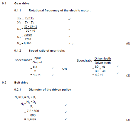
9.1.1 Rotational frequency of the electric motor:
9.1.2
Speed ratio of gear train:
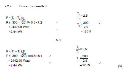
9.3 The volume of gas can be changed by the altering of ...
- its pressure √
- its temperature √
- both its pressure and temperature √ (Any 2 x 1) (2)
9.4 Definition of Boyle's law
The volume of a given mass√ of gas is inversely proportional to the pressure√ on it, if the temperature remains constant√ (3)
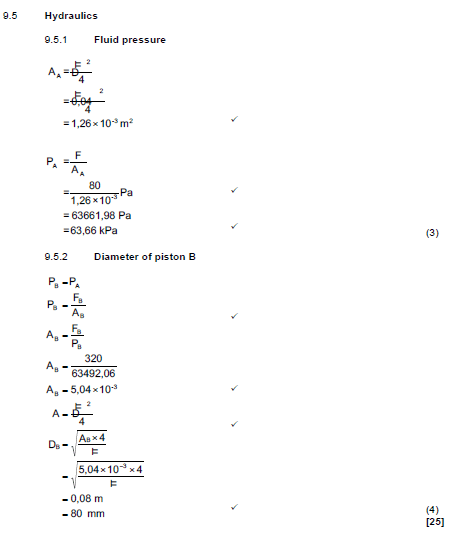
9.5
Hydraulics
9.5.1
QUESTION 10: TURBINES
10.1 Water turbine blades
To supply water pressure √ to the turbine √ (2)
10.2 Reverse flow
- Deriaz √
- Francis √ (2)
10.3 Supercharger
- Roots√
- Twin screw√
- Centrifugal √
- Vane √ (Any 2 x 1) (2)
10.4 Turbocharger
- Exhaust gases drive the turbine √
- The turbine drives a compressor via a common shaft√
- The compressor forces √ compressed air above atmospheric pressure into the cylinder √
- Exhaust gases leave system through the exhaust pipe √ (5)
10.5 Supercharger over turbocharger
- Do not suffer lag √
- More efficient at low revolution per minute. √
- Does not require extensive exhaust modification.√
- No special shutdown procedure is required. √ (Any 2 x 1) (2)
10.6 Lag
Lag is the delay √ between pressing the accelerator pedal √ and feeling the pressure building up.√ (3)
10.7 Supercharger drive
- Belt drive √
- Gear drive √
- Chain drive √ (Any 2 x 1) (2)
10.8 Gas turbine disadvantages
- Cost is much greater than for a similar-sized reciprocating engine since the materials must be stronger and more heat resistant. √
- Manufacturing operations are also more complex. √
- Usually less efficient than reciprocating engines, especially at idling speed. √
- Delayed response to changes in power settings. √
(Any 2 x 1) (2)
[20]
TOTAL: 200