Mechanical Technology: Welding and Metalwork Grade 12 Memorandum - NSC Exams Past Papers and Memos September 2019 Preparatory Examinations
Share via Whatsapp Join our WhatsApp Group Join our Telegram GroupMARKING GUIDELINE
QUESTION 1: MULTIPLE-CHOICE QUESTIONS (GENERIC)
1.1 C (1)
1.2 A (1)
1.3 B (1)
1.4 D (1)
1.5 A (1)
1.6 C (1) [6]
QUESTION 2: SAFETY (GENERIC)
2.1 Reasons for wearing a helmet:
- Protects your eyes from ultra violet rays and infra-red rays. (2)
2.2 Angle grinder safety:
- Safety guard must be in place before grinding.
- Protective shields must be placed around the object being ground to protect passers-by.
- Use the correct grinding disc for the job.
- Do not use excessive force while grinding and cutting.
- Make sure there are no cracks on the disc before you start a job.
- Protective clothing and eye protection are essential. (Any 2) (2)
2.3 Maximum gap – bench grinder:
- 3 mm (1)
2.4 Band saw safety:
- Wear safety glasses or a face shield.
- Wear protective footwear when required.
- Make sure all guards are in place.
- Check for correct tension on the blade.
- Use blades that are sharp, properly set and suitable for the job.
- Keep the floor clean and free of obstructions or clutter. (Any 3) (3)
2.5 Gas cylinder safety precautions:
- Always store and use gas cylinders in an upright position.
- Never stack cylinders on top of one another.
- Do not bang or work on the cylinders.
- Never allow cylinders to fall.
- No oil and grease should come into contact with gas cylinders or fittings.
- Keep the caps on the cylinders for protection. (Any 2) (2) [10]
QUESTION 3: MATERIALS (GENERIC)
3.1 Quenching:
- Quenching means to cool the heated material rapidly.
- Cooling the material to room temperature.
- Water is normally used for low and medium carbon steels.
- Oil is used on high carbon and alloy steel.
- Extreme cooling brine is used. (Any 3) (3)
3.2 Difference between brine and salt water:
- Brine hardens steels better than fresh water, salt inhibits the water from dissolving into atmospheric gas.
- Salt water does not vaporise as quickly as fresh water. (2)
3.3 Purpose for case-hardening:
- It hardens the surface.
- It provides a wear resistant surface.
- Strengthens core to withstand applied loads. (3)
3.4 Methods of case-hardening:
- Mild steel can be surface hardened by heating to its critical range and immersing in case hardening compound. Carbon is absorbed into surface layer of steel.
- Mild steel can be heated in an atmosphere of nitrogen called Nitriding. (Any 1 x 2) (2)
3.5 Difference between annealing and normalising:
- Annealing requires steel to cool down over an extended period thus resulting in an internal structural change in the steel, making it softer.
- Normalising merely removes work-related stresses. (4) [14]
QUESTION 4: MULTIPLE-CHOICE QUESTIONS (SPECIFIC)
4.1 C (1)
4.2 D (1)
4.3 A (1)
4.4 B (1)
4.5 A (1)
4.6 C (1)
4.7 A (1)
4.8 B (1)
4.9 C (1)
4.10 C (1)
4.11 A (1)
4.12 B (1)
4.13 A (1)
4.14 C (1) [14]
QUESTION 5: TERMINOLOGY (TEMPLATES) (SPECIFIC)
5.1 Roof truss:
A – Purlins
B – Internal bracing member/s
C – Ridging
D – Roof covering
E – Rafter (5)
5.2 Fillet weld on T-joint: (7)
(7)
5.3 Dimensions of the material: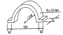
Average Ø = inside Ø + sheet thickness
Average Ø = 476 mm + 12 mm
Average Ø = 488
Average perimeter = ? x Average Ø
Average perimeter = (? x 488 mm) ÷ 2
Average perimeter = 766,54 mm
Total length needed = 766,54 + 60 mm + 60 mm
Total length needed = 886,55 mm
Round off to 887 mm (6)
5.4
- Flange templates
- Web templates
- Strip templates (3)
5.5
- Hand saws
- Chisels
- Plane
- Cordless drill and drill bits
- Steel tap
- Straight edge
- Compass, trammels
- Squares
- Protractors
- Chalk lines etc. (Any 2) (2) [23]
QUESTION 6: TOOLS AND EQUIPMENT (SPECIFIC)
6.1 Danger of oil – Oxy-Acetylene:
- It can catch alight. (1)
6.2 Uses of a bench grinder:
- To sharpen cutting tools and drill bits.
- To remove rough edges.
- To remove excess material. (3)
6.3 6.3.1 Spot welding equipment:
- Uses the heating effect, which occurs when a current flows through a resistance, to fuse two plates together. (3)
6.3.2 Punch and shearing machine:
- Are being used for cutting steel profiles and punching holes into steel plates. (4)
6.4 Types of rolling machines:
- Horizontal pyramid rolls
- Off-set pinch rolls
- Vertical rolls (3)
6.5
- Centre screw used to adjust the die.
- Two side screws used to secure the die. (2)
6.6 Consequences of soft material-bench grinder:
- The soft material lodges in the pores of the wheel and expands.
- Pieces can dislodge when the wheel is revolving at high speed causing injury. (2) [18]
QUESTION 7: FORCES (SPECIFIC)
7.1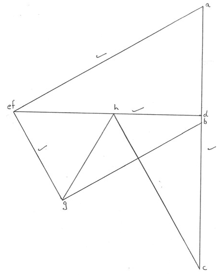
MEMBER | STRUT | TIE | FORCE | |
AE | √ | 15,3 N | √ | |
BG | √ | 11,3 N | √ | |
CH | √ | 12,2 N | √ | |
FG | √ | 6,9 N | √ | |
EF | ||||
DE | √ | 13,25 N | √ | |
DF | √ | 13,25 N | √ | |
DH | √ | 6,2 N | √ | |
GH | √ | 7 N | √ |
(20)
7.2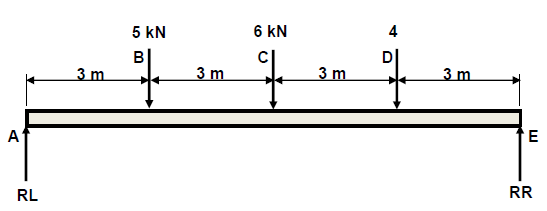
7.2.1 Reactions at the supports RL and RR
Moments about RR
- RL x 12 = (5 x 9) + (6 x 6) + (4 x 3)
RL x 12 = 45 + 36 + 12
RL = 93
12
RL = 7,75 N
Reactions about RL
RR x 12 = (4 x 9) + (6 x 6) + (5 x 3)
RR x 12 = 36 + 36 + 15
RR = 87
12
RR = 7,25 Kn (6)
7.2.2 Shear forces:
- ??? = 0 Kn
??? = 7,75 – 5
= 2,75 Kn
??? = 7,75 – 5 – 6
= - 3, 25 Kn
??? = 7,75 – 5 – 6 – 4
= - 7,25 Kn
??? = 7,75 – 5 – 6 – 4 + 7,75
= 0 kN (5)
7.2.3 Bending moments:
- BMA = 0 kN.m
BMB = (7,75×3)
= 23,25 kN.m
BMC = (7,75×6)-(5× 3)
= 46,5 ×15
= 31,5 kN.m
BMD = (7,75×9)-(5× 6)- (6 × 3)
= 69,75 - 30 -18
= 21,75 kN.m
BME = (7,75×12)-(5× 9)- (6 × 6)-(4× 3)
= 93 - 45 - 36 -12
= 0 kN.m (5)
7.2.4 Shear force diagram: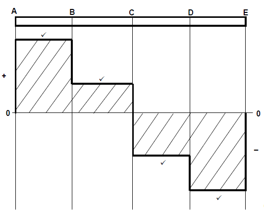 (4)
(4)
7.2.5 Bending moment diagram: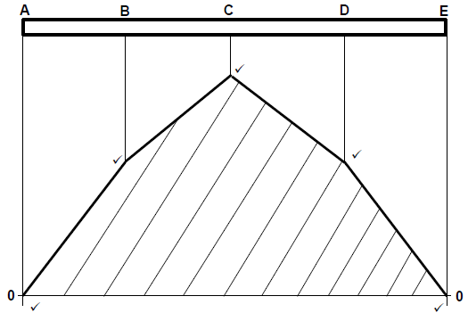 (5)
(5)
[45]
QUESTION 8: JOINING METHODS (INSPECTION OF WELD) (SPECIFIC)
8.1 Welding spatter:
It is molten material that are generated at or near the welding arc.
Causes: Disturbance in the molten weld pool during the transfer of wire into the weld.
- Voltage too low
- Amperage too high (4)
8.2 Liquid dye test:
- Clean the surface to be inspected and spray the liquid dye to penetrate into the surface.
- Allow liquid dye to penetrate.
- Remove excess dye with cleaner.
- Spray a developer onto the surface to bring out the colour.
- Areas where the dye has penetrated (defects) will show up clearly. (5)
8.3
8.3.1 Undercutting:
- Improper settings of equipment
- Welding speed too fast
- Current too high (Any 2) (2)
8.3.2 Slag inclusion:
- Incorrect current settings
- Included angle too narrow
- Rapid chilling
- Previous weld slag has not been removed (Any 2) (2)
8.3.3 Porosity:
- Atmospheric contamination
- Surface contamination
- Dirty or wet electrodes when arc welding
- Rusted MIG wire (Any 2) (2)
8.3.4 Lack of fusion:
- Poor welding technique
- Travel speed is too slow
- Using a very wide weld joint
- Weld current too low (Any 2) (2)
8.4
- Correct flame for the work on hand
- Correct angle of blowpipe and rod
- Depth of fusion and amount of penetration
- Rate of progress along the joint (Any 3) (3)
8.5 Types of cracks:
- Heat affected zone cracks.
- Centreline cracks.
- Crater cracks.
- Transverse cracks. (2)
8.6 Nick-break test:
- It tests for internal welding defects. (1) [23]
QUESTION 9:
JOINING METHODS (STRESSES AND DISTORTION) (SPECIFIC)
9.1 Weld distortion is the warping of the base plate caused by heat from the welding arc / flame. (2)
9.2 Distortion and residual stress:
- Heat present in the weld.
- Qualities of parent metal, filler rod or electrode.
- Shape and size of weld.
- Number of successive welds runs.
- Comparative weight of weld metal and parent metal.
- Type of welding joint used. (Any 3) (3)
9.3 Reduce distortion:
- Do not over weld.
- Intermittent welding.
- Place welds near the neutral axis.
- Use as few passes as possible.
- Use back step welding.
- Anticipate the shrinkage forces.
- Planning the welding sequence.
- Using strong backs.
- Using clamps, jigs and fixtures. (Any 3) (3)
9.4 Steel groups:
- Low carbon steel: 0,15 – 0,30% carbon.
- Medium carbon steel: 0,31 – 0,70% carbon.
- High carbon steel: 0,71 – 1,5 % carbon. (6)
9.5 Difference between cold working and hot working of steel: Cold working is when deformation of steel takes place below the recrystallisation temperature of the steel.
Hot working is when deformation of steel takes place above the recrystallisation temperature of the steel.(4) [18]
QUESTION 10: MAINTENANCE (SPECIFIC)
10.1 Locking out of large machines before maintenance:
- Due to the danger associated with large machines
- To ensure that isolation switches are switched off
- To ensure that switches are locked out and tagged to inform others that maintenance work is being done
- To ensure that nobody can turn the machine on while maintenance is being done (Any 2 x 1) (2)
10.2 Tagging plates:
- It has multiple holes so that more than one technician can lock out the machine simultaneously. (1)
10.3 Major and minor services for power-driven guillotine:
- Major service allows for on-going service procedures that are designed to maintain the guillotines in premium working conditions.
- Minor service is designed to minimise major mechanical and electrical failures, by employing the principle of preventative maintenance. (2)
10.4 Maintenance guidelines for a pedestal drilling machine:
- Visual checks of electrical wiring, switches, etc.
- Verify that all guards are secure and function correctly.
- Ensure workspace is clear.
- Confirm availability and conditions of PPE.
- Lubricate moving parts.
- Use moisture-penetrating oil spray to prevent rust.
- Check for availability of specific tools.
- Check the run-out of the spindle.
- Inspect belts for wear.
- Ensure the drive belt is correctly tensioned.
- Check the condition of the rack and pinion mechanisms and lubricate.
- Ensure cuttings are removed.
- Inspect the Morse taper sleeves for burrs/scratches.
- Check the security of machine mountings. (Any 2) (2)
10.5 Overloading a punch and shearing machine:
- Dulling or breaking blades/punches.
- Putting strain on the motor and drive mechanism. (Any 1) (1) [8]
QUESTION 11: TERMINOLOGY (DEVELOPMENT) (SPECIFIC)
11.1 Conical hopper:
11.1.1 Vertical height (DE):
- tanθ= opposite
adjacent
DE=tan70º×EC
= 2,75×1
= 2,75 m (2)
11.1.2 Main radius (AC):
- Cos Ɵ= adjacent
hypotenuse
AC = ??
??? 70°
= 2
0,34
= 5,88 m (2)
11.1.3 Small radius (AD):
- Cos Ɵ = adjacent
hypotenuse
DC = ??
??? 70°
= 1
0,34
= 2,94 m
Now AD can be calculated.
AD = AC – DC
= 5,88 – 2,94
= 2,94 m (3)
11.1.4 Circumference:
- Circumference: = ? x GD
= ? × 4
= 12,57 m (2)
11.2 Square-to-round transition piece:
11.2.1 The true length FG is firstly needed to draw the pattern:
- IK = 300 (2 units)
IH = 150 (1 units)
HK = 1 √3 (1 unit x √3 )
The true length FG:
Plan length FG = FG – GK
= 400 – 300
= 100 mm
The true length FG is equal to H′F
H′?2 = ?′?2 + ??2
= 8002 + 1002
?′? = √650 000
True length FG = 806 mm (5)
11.2.2 To determine the plan length CI, the sides CE and EI of triangle CEI must be calculated.
- CE = CF – EF
= 400 – 150
= 250 mm
But EI = FH
FH = FK – HK
= 400 – 259,8
= 140,2 mm
True Length (CI) = ??2 + ??2
= 2502 + 140,22
= √82156,04
= 286,63 mm (4)
11.2.3 JI is one-twelfth of the circumference
- Circumference = ? x GD
= ? x 600
= 1 884,9 mm
1 Circumference = 1884,9
12 12
= 157,1 mm (3) [21]
TOTAL: 200