ELECTRICAL TECHNOLOGY GRADE 12 QUESTIONS - NSC PAST PAPERS AND MEMOS NOVEMBER 2016
Share via Whatsapp Join our WhatsApp Group Join our Telegram GroupELECTRICAL TECHNOLOGY
GRADE 12
NATIONAL SENIOR CERTIFICATE
NOVEMBER 2016
INSTRUCTIONS AND INFORMATION
- This question paper consists of SEVEN questions.
- Answer ALL the questions.
- Sketches and diagrams must be large, neat and fully labelled.
- Show ALL calculations and round off answers correctly to TWO decimal places.
- Number the answers correctly according to the numbering system used in this question paper.
- You may use a non-programmable calculator.
- Show the units for all answers of calculations.
- A formula sheet is provided at the end of this question paper.
- Write neatly and legibly.
QUESTION 1: OCCUPATIONAL HEALTH AND SAFETY
1.1 State ONE unsafe action that may lead to an accident in a workshop. (1)
1.2 Give ONE example of a dangerous practice in a workshop. (1)
1.3 Give TWO examples of the type of behaviour that would contribute to good work ethics. (2)
1.4 Name TWO first-aid procedures that should be followed when a person has sustained burn wounds. (2)
1.5 Describe why proper ventilation is important in a workshop. (2)
1.6 State TWO steps that must be taken when doing a risk analysis. (2)
[10]
QUESTION 2: THREE-PHASE AC GENERATION
2.1 Determine the value of the phase voltage in a delta-connected system if the line voltage is 380 V. (2)
2.2 Draw a neat, labelled voltage phasor diagram that represents a three-phase delta-connected system. (3)
2.3 A star-connected alternator generates 20 kVA at a power factor (p.f.) of 0,87 lagging. The line voltage is 380 V.
Given:
S = 20 kVA
VL = 380 V
p.f. = 0,87 lagging
Calculate the:
2.3.1 Current delivered by the alternator at full load (3)
2.3.2 Power rating of the alternator (3)
2.4 State the function of a kilowatt-hour meter. (2)
2.5 State TWO methods used to improve the power factor of a resistive inductive load. (2)
2.6 Refer to FIGURE 2.1 and answer the questions that follow.
Given:
P1 = 120 W
P2 = 50 W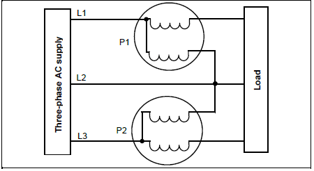
FIGURE 2.1: TWO-WATTMETER METHOD
2.6.1 Calculate the power consumed by the load. (3)
2.6.2 State TWO advantages of using the two-wattmeter method when measuring the power. (2)
[20]
QUESTION 3: THREE-PHASE TRANSFORMERS
3.1 State TWO functions of the oil used in oil-filled transformers. (2)
3.2 Name TWO losses that occur in transformers. (2)
3.3 State TWO advantages of a three-phase transformer over a single-phase transformer. (2)
3.4 Explain why a transformer cannot step up power. (2)
3.5 Describe what would happen to the primary current of a step-down transformer if the load of the transformer were increased. (3)
3.6 A 20 kVA three-phase transformer has a delta-connected primary and a star-connected secondary. The primary line voltage is 6,6 kV and the secondary line voltage is 380 V.
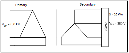
FIGURE 3.1: THREE-PHASE TRANSFORMER
Calculate the:
3.6.1 Primary line current (3)
3.6.2 Secondary phase voltage (3)
3.6.3 Transformation ratio (3)
[20]
QUESTION 4: THREE-PHASE MOTORS AND STARTERS
4.1 Refer to FIGURE 4.1 and answer the questions that follow.
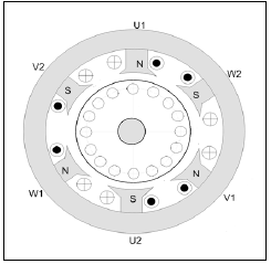
FIGURE 4.1: THREE-PHASE SQUIRREL-CAGE INDUCTION MOTOR
4.1.1 State whether there is an electrical connection between the stator and rotor. (1)
4.1.2 Describe the operation of the motor. (7)
4.1.3 Describe what would happen to the motor if one phase of the stator winding were an open circuit. (3)
4.2 State TWO advantages of a three-phase induction motor over a single-phase induction motor. (2)
4.3 Describe why it is important to check the insulation resistance between the stator windings before energising a motor. (3)
4.4 State ONE mechanical test that must be carried out on a motor before it is energised. (1)
4.5 A three-phase induction motor is connected across a 380 V/50 Hz supply. The motor has 18 poles and a slip of 4%.
Given: VL = 380 V
f = 50 Hz
p = 3
slip = 4%
Calculate the:
4.5.1 Synchronous speed (3)
4.5.2 Rotor speed (3)
4.6 A three-phase delta-connected motor draws a current of 8,5 A when connected to a 380 V/50 Hz supply. The motor has a power factor of 0,8 and an efficiency of 95%.
Given: VL = 380 V
IL = 8,5 A
f = 50 Hz
p.f. = 0,8
ŋ = 95%
Calculate the:
4.6.1 Input kVA of the motor at full load (3)
4.6.2 Active power output of the motor at full load (3)
4.7 Describe the function of an overload unit in a motor starter. (3)
4.8 FIGURE 4.2 represents the control circuit of an automatic sequence starter.
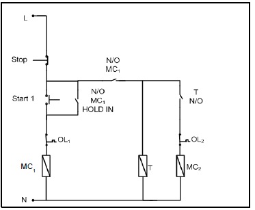
FIGURE 4.2: CONTROL CIRCUIT OF AN AUTOMATIC SEQUENCE STARTER
4.8.1 State ONE practical application of the automatic sequence starter. (1)
4.8.2 Describe what would happen to motor 1 (MC1) if the contact labelled N/O MC1 HOLD IN were faulty and did not close. (2)
4.8.3 Describe the starting sequence of the starter. (5)
[40]
QUESTION 5: RLC
5.1 Distinguish between the reactance and impedance in an RLC circuit. (4)
5.2 Explain what the phase angle indicates. (2)
5.3 FIGURE 5.1 shows the relationship between the inductive reactance and the capacitive reactance against frequency in an RLC series circuit. Answer the questions that follow.
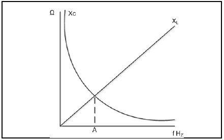
FIGURE 5.1: FREQUENCY RESPONSE CURVE
5.3.1 Explain the effect of frequency on the impedance of the circuit at point A. (2)
5.3.2 Calculate the frequency at point A if the circuit included a 50 μF capacitor and a 0,1 H inductor.
Given:
C = 50 μF
L = 0,1 H (3)
5.4 The series circuit in FIGURE 5.2 consists of a capacitor with a capacitive reactance of 20 Ω, an inductor with an inductive reactance of 40 Ω and a resistor with a resistance of 30 Ω connected across a 240 V/50 HZ supply.
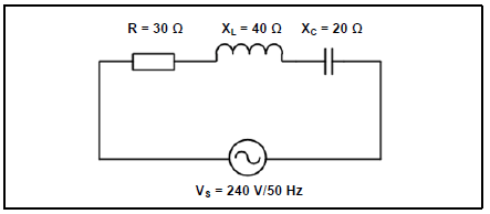
FIGURE 5.2: RLC SERIES CIRCUIT
Given:
XC = 20 Ω
XL = 40 Ω
R = 30 Ω
VS = 240 V
f = 50 Hz
Calculate the:
5.4.1 Impedance of the circuit (3)
5.4.2 Phase angle of the circuit (3)
5.5 A capacitor with a capacitance of 1,47 μF is connected in parallel with a 1 kΩ resistor across a 20 V AC supply. Calculate the supply frequency if the capacitor draws a current of 10 mA.
Given:
C = 1,47 μF
R = 1 kΩ
VS = 20 V
IC = 10 mA (3)
[20]
QUESTION 6: LOGIC
6.1 Identify THREE programming methods used in programmable logic controllers (PLCs). (3)
6.2 Name TWO input devices that may be connected to the input stage of a PLC. (2)
6.3 State THREE disadvantages of a hardwired system in comparison with a PLC system. (3)
6.4 Explain how low-current devices, such as transistors, may be activated by the output of a PLC. (2)
6.5 Write the simplified Boolean equation for the expression below. Use a four-variable Karnaugh map.![]() (11)
(11)
6.6 Simplify the following Boolean equation by using Boolean algebra:![]() (5)
(5)
6.7 Refer to FIGURE 6.1.
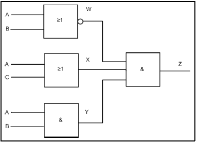
FIGURE 6.1: GATE NETWORK
Determine the output at the following points:
6.7.1 W (1)
6.7.2 X (1)
6.7.3 Y (1)
6.7.4 Z (2)
6.8 Name the following ladder logic symbols:
6.8.1 ![]() (1)
(1)
6.8.2  (1)
(1)
6.8.3![]() (1)
(1)
6.9 Refer to FIGURE 6.2 and answer the questions that follow.
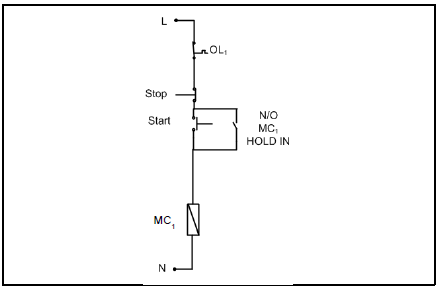
FIGURE 6.2: DOL STARTER
6.9.1 Draw the ladder logic diagram that will execute the same function in a PLC system. (5)
6.9.2 Give ONE example where the circuit in FIGURE 6.2 may be used in an electrical application. (1)
[40]
QUESTION 7: AMPLIFIERS
7.1 State THREE ideal characteristics of an operational amplifier (op amp) besides unconditional stability. (3)
7.2 Describe the term unconditional stability with reference to an ideal op amp. (2)
7.3 Describe the term positive feedback. (3)
7.4 Name the type of op-amp circuit that uses positive feedback. (1)
7.5 State TWO advantages of negative feedback. (2)
7.6 Refer to FIGURE 7.1 and draw the output of the ideal op amp.
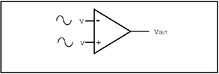
FIGURE 7.1: OP AMP (3)
7.7 Refer to FIGURE 7.2 and answer the questions that follow.
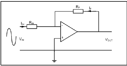
FIGURE 7.2: OP-AMP CIRCUIT
7.7.1 Identify the op-amp circuit above. (1)
7.7.2 Draw the input signal and output signal on the same axis. (3)
7.7.3 Calculate the voltage gain if the feedback resistance is 12 kΩ and the input resistor has a value of 2,2 kΩ. (3)
7.7.4 Calculate the output voltage if an input signal of 5 V is applied to the op amp.(3)
7.7.5 Describe what happens to the gain of the op amp if the value of RF decreases. (2)
7.8 Refer to the summing op-amp circuit in FIGURE 7.3 and answer the questions that follow.
Given:
V1 = 2 V
V2 = -10 V
V3 = 5 V
R1 = R2 = R3 =RF
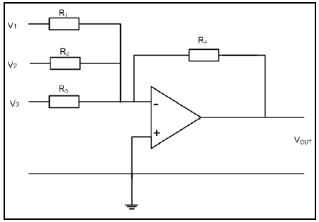
FIGURE 7.3: SUMMING OP-AMP CIRCUIT
7.8.1 Describe the function of the summing op-amp circuit. (3)
7.8.2 Calculate the output voltage. (3)
7.9 Refer to the monostable multivibrator op-amp circuit in FIGURE 7.4 and answer the questions that follow.
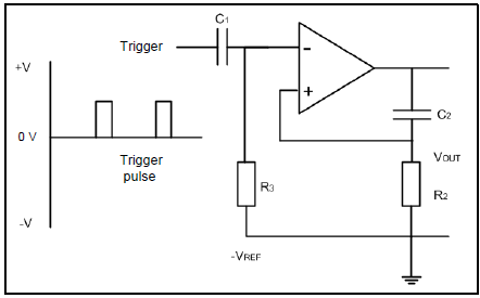
FIGURE 7.4: MONOSTABLE MULTIVIBRATOR OP-AMP CIRCUIT
7.9.1 State the function of the circuit above. (1)
7.9.2 Draw the input trigger pulse and directly below that, draw the output to show the correct timing in relation to the input. (7)
7.9.3 Calculate the time delay if R2 = 12 kΩ and C2 = 47 μF. (3)
7.10 Calculate the oscillating frequency of an RC oscillator with three RC networks. The resistors and capacitors are identical and have values of 10 kΩ and 250 pF respectively. (3)
7.11 Describe the function of an op amp when used in a differentiator circuit. (2)
7.12 Describe how an op amp is packaged. (2)
[50]
TOTAL: 200
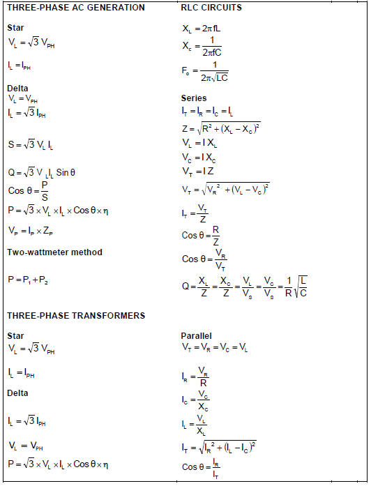
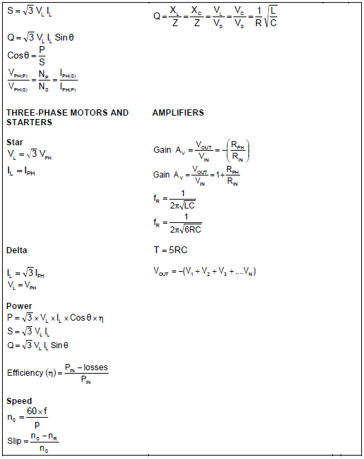
FORMULA SHEET