ELECTRICAL TECHNOLOGY GRADE 12 MEMORANDUM - NSC PAST PAPERS AND MEMOS 2016
Share via Whatsapp Join our WhatsApp Group Join our Telegram GroupELECTRICAL TECHNOLOGY
GRADE 12
MEMORANDUM
NATIONAL SENIOR CERTIFICATE
NOVEMBER 2016
INSTRUCTIONS TO THE MARKERS
- All questions with multiple answers imply that any relevant, acceptable answer should be considered.
- Calculations:
2.1 All calculations must show the formulae.
2.2 Substitution of values must be done correctly.
2.3 All answers MUST contain the correct unit to be considered.
2.4 Alternative methods must be considered, provided that the correct answer is obtained.
2.5 Where an incorrect answer could be carried over to the next step, the first answer will be deemed incorrect. However, should the incorrect answer be carried over correctly, the marker has to re-calculate the values, using the incorrect answer from the first calculation. If correctly used, the candidate should receive the full marks for subsequent calculations. - This memorandum is only a guide with model answers. Alternative interpretations must be considered and marked on merit. However, this principle should be applied consistently throughout the marking session at ALL marking centres.
QUESTION 1: OCCUPATIONAL HEALTH AND SAFETY
1.1
- Working on a live system with exposed conductors.
- Working with portable electric equipment that is not insulated correctly.
- Using electrical machines without using the required safety equipment or clothing.
- Not using guards and goggles or other safety equipment.✓
Note: An unsafe action is where an incorrect action may inadvertently lead to an accident or injury. This case relates to a human related intervention. (1)
1.2
- The incorrect use of etching acid and other chemicals.
- The unsafe use of power tools.
- Not using guards and goggles or other safety equipment.
- Working on a live system with exposed conductors
Note: Dangerous practice relates to tasks that are inherently dangerous, but if actioned correctly would not lead to an accident or injury. This case relates to the working environment. (1)
1.3
- Good attendance.✓
- Respect for fellow workers.✓
- Respect for seniors.
- Respect for work environment. (2)
1.4
- Remove the person from the heat source.✓
- Remove any burnt clothing if not stuck to the victim. ✓
- Run cool water on the burnt area; do not use ice or grease.
- Inform people in authority. (2)
1.5 Proper ventilation is essential to keep people working efficiently✓ the use of chemicals can make people drowsy and create an unsafe condition.✓ (2)
1.6
- Involve the workers✓
- Identify hazards ✓
- Record your findings
- Consider good practice in your industry (2)
[10]
QUESTION 2: THREE-PHASE AC GENERATION
2.1 VPH = VL✓
=380V✓
NOTE:
If the candidate indicates V 380VPH=, award 2 marks. (2)
2.2
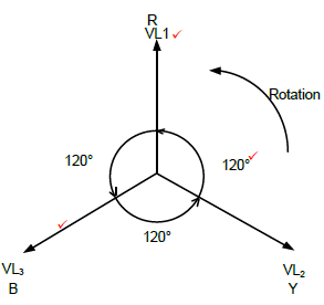
NOTE:
1 mark = Drawing phasor diagram
1 mark = Labelling the phases
1 mark = Labelling the angle between the phases
Markers may consider rotation if a learner leaves out one aspect mentioned above.
Alternative Method: Closed Form Phasor Diagram
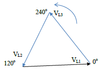 (3)
(3)
2.3
2.3.1 IL = S ✓
√3 x VL
=20 x 103
√3 x 380✓
30,39A✓ (3)
2.3.2
P = √3 VLIL???? ✓
= √3 x 380 x 30,39 x 0.87 ✓
= 17,4kW ✓
Alternative Method:
???? = P
S
P = S x ????
P = 20000 x 0,87
P = 17,4 kW (3)
2.4 The function of a kWh meter is to measure the amount of energy power consumed ✓ by a consumer over a period of time. ✓
Alternative – To measure energy. (2)
2.5 Adding power factor correcting capacitors in parallel with the load.✓
Use synchronous motors. ✓ (2)
2.6
2.6.1 Pin = P1 + P2✓
= 120 + 50✓
= 170 W✓ (3)
2.6.2
- Only two watt meters are required instead of three✓
- The power of balanced and unbalanced load may be measured✓
- The power factor of a balanced load can be determined. (2)
[20]
QUESTION 3: THREE-PHASE TRANSFORMERS
3.1
- Insulation purposes ✓
- Cooling purposes✓ (2)
3.2
- Copper losses✓
- Iron losses✓
- Dielectric losses
- Stray losses (2)
3.3
- Can be connected in delta ✓to deliver power to transmission lines
- Can be connected in star ✓to deliver power to consumers
- Delivers more power for the same size
- Can deliver both phase voltage and line voltage (2)
3.4 A transformer cannot step up power because all transformers have internal losses✓ that will reduce the output power. ✓
In an ideal transformer input and output power ✓ is the same. ✓ This is due to the current (and Power) of an installation being determined by the load not the transformer. (2)
3.5 If the load of the transformer is increased the transformer will draw more power from the supply✓ to deliver the increased load. ✓As the voltage is constant the primary current will increase. ✓ (3)
3.6
3.6.1 IPL = S ✓
√3VPL
= 20000
√3 x 6600 ✓
= 1,75A ✓ (3)
3.6.2 ??? = ?? ✓
√3
???=380 ✓
√3
=219,39?✓ (3)
3.6.3 NP = VPH(P)✓
NS VPH(S)
= 6600
219,39 ✓
TR = 30:1 ✓ (3)
[20]
QUESTION 4: THREE-PHASE MOTORS AND STARTERS
4.1
4.1.1
- There is no connection ✓
- The connection is magnetic and not electrical by nature (1)
4.1.2
- A three-phase voltage supply is connected across the stator windings. ✓
- This sets up three-phase currents flowing in the stator windings. ✓
- The currents create a rotating magnetic field in the stator. ✓
- The rotating magnetic field sweeps across the rotor conductors. ✓
- This action induces an emf across the conductors in the rotor, which results in currents flowing in the conductors. ✓
- The induced rotor current in turn creates a magnetic field around the rotor. ✓
- The two magnetic fields interact causing the rotor to rotate. ✓ (7)
4.1.3 The motor will still rotate ✓but would not develop ✓the correct torque (output power). ✓ (3)
NOTE:
This question may have different interpretations.
The motor may not develop enough torque to turn the motor at all, depending on its efficiency and torque rating.
4.2 They require less maintenance as they do not have as many parts as a single phase motor✓
For the same size frame as a single phase motor they deliver a higher torque.✓ (2)
4.3 To determine that the integrity of the insulation is sound✓ so that the motor may be energised✓without an electrical fault occurring. ✓ (3)
4.4
- Check for secure mountings. ✓
- Check for cracked frame.
- Check smooth rotation. (1)
4.5
4.5.1 nS = 60 xf ✓
p
= 60 x 50 ✓
3
= 1000r/min ✓ (3)
4.5.2 nR = nS (1-S) ✓
nR = 1000(1-0,04)✓
nR = 960r/min✓(3)
NOTE:The answers are rounded off as the answers are given in r/min. Learners must be given credit whether they have or haven't rounded off.
4.6
4.6.1 √3 x VL x IL✓
= √3 x 380 x 8,5 ✓
=5,59 kVA✓(3)
4.6.2 P = √3 x VL x IL x ???? x η ✓
√3 x 380 x 8,5 x 0,8 x0,95 ✓
= 4,25 kW✓ (3)
4.7 The overload unit relay offers protection to the motor and operator ✓under fault conditions.✓ When activated it will remove power from the main contactor disabling the circuit. ✓ (3)
4.8
4.8.1 Conveyor belt. ✓Start the first drive motor and after a pre-determined time start the second drive motor. (1)
NOTE: Any viable explanation must be accepted.
4.8.2
- If the contacts were faulty when the start button is depressed the contactor MC1 would energise motor 1. ✓
- When the start button is released the motor would de-energise as the power is removed from MC1✓ (2)
4.8.3
- When N/O Start button is pressed, coil MC1 energises, thus starting motor 1. ✓
- Subsequently the contact N/O (Hold-in) will close keeping MC1 energised after the Start button is released. ✓
- At the same time, N/O MC1 closes, thus energising the coil of the timer contactor (T). ✓
- The timer will time through a pre-determined value, after which T N/O will close energising MC2✓
- When MC2 is energised , motor 2 will start ✓ (5)
[40]
QUESTION 5: RLC
5.1 Reactance is the opposition offered to the flow of current in an AC circuit✓ by either a capacitor or an inductor or both✓. Impedance is the opposition offered to the flow of current in an AC circuit✓ by the combination of the resistance and the reactance of the circuit✓. (4)
5.2 The phase angle indicates the angle between the supply voltage✓ and the current ✓this indicates the power factor of the circuit. (2)
5.3
5.3.1
- Point A indicates the resonant frequency of the graph.
- At resonance it can be seen that XL = XC.
- The effect of XL and XC are opposites resulting in reactance being zero at resonance. ✓
- As a result thereof Z = R at resonance. ✓
- Impedance in a series circuit at resonance is a minimum. (2)
5.3.2
 (3)
(3)
5.4
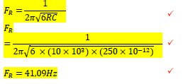
5.4.1 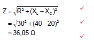 (3)
(3)
5.4.2 θ = cos-1 R ✓
Z
=cos-1 30 ✓
36,05
=33,68º ✓ (3)
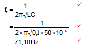
5.5 VC = ICXC
f = Ic ✓
Vc x 2 x π x C
= 10 x 10-3 ✓
20 x 2 x π 1,47 x 10-6
= 54,13Hz ✓(3)
NOTE: This is a complex calculation and is rated as a higher order, difficult question.
[20]
QUESTION 6: LOGIC
6.1
- Ladder diagrams✓
- Function block diagram✓
- Sequential flow chart✓
- Instruction list
- Structured text
- The learner may refer to programming devices which in this context would be acceptable as well. (3)
6.2
- Sensing device✓
- Switches✓
- Pushbuttons
- Limit switches
- Pressure switches (any two) (2)
6.3
- Hardwired system would use many relays, cam controllers, timers, and counters.✓
- Control panels would have to be re-wired when production models were changed.✓
Hardwired system physically takes up more space than PLC systems.✓ - Hardwired systems requires more maintenance (3)
6.4 A low current device can be activated by connecting it via the PLC output relay✓ to a source✓
Transistor output PLC's can be connected directly as it delivers an output voltage via a transistor. (2)
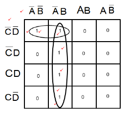
6.5
NOTE:
Please take note of the mark allocation indicated for grouping.
Be aware of the alternative method of populating the Karnaugh map when labelling is different.
![]() (11)
(11)
6.6 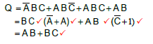 (5)
(5)
6.7
6.7.1 ![]() (1)
(1)
6.7.2 X = A + C (1)
6.7.3 Y = A.B (1)
6.7.4 ![]() (2)
(2)
6.8
6.8.1 Normally open contact / switch ✓ Input
Input (1)
6.8.2 Normally closed contact✓ Input
Inverted input (1)
6.8.3 (Coil) output✓
Output (1)
6.9
6.9.1 Alternative circuit using NON Inverted inputs are acceptable.
 (5)
(5)
Note: One mark may be awarded for a correct drawing with NO labels.
6.9.2 Motor starter✓ (1)
[40]
QUESTION 7: AMPLIFIERS
7.1
- Open loop voltage gain is infinite ✓
- Input impedance is Infinite✓
- Output impedance is zero ✓
- Infinite bandwidth (3)
7.2 Unconditional stability means that the operation of the amplifier is not✓ influenced by temperature changes. ✓ (2)
7.3 Positive feedback occurs in an amplifier circuit when a portion of the output✓ signal is fed back into the input.✓ The portion of the wave fed back will be in phase with the input therefore added to the input waveform. (3)
7.4 Oscillator circuit. ✓ (1)
7.5
- The bandwidth increased. ✓
- The level of noise (hiss) decreased ✓
- The gain is predictable
- The deformation of the input signal is reduced (2)
7.6  (3)
(3)
7.7
7.7.1 Inverting op-amp ✓ (1)
7.7.2 Must show amplification inversion and same frequency.
NOTE: It has been found that some PDF’s and printouts do not show all the graphics.
Be lenient when considering drawings on separate axis. All three conditions however should be met. (3)
7.7.3? ?=−?? ✓
???
??=−12000✓
2200
??=−5,45✓ (3)
7.7.4 ??=???? ✓
???
????=??×??? ✓
????=−5,45×5 ✓
????=−27,25? (3)
7.7.5 If RF was decreased the voltage gain of the op-amp will decrease✓
as it is directly proportional the value of the feedback resistor. ✓ (2)
7.8
7.8.1 This circuit allows for various input signal voltages to be fed into the circuit ✓thus producing a single output signal ✓that is the sum of the input signals. ✓(3)
7.8.2
????=−(?1+?2+?3)
????=−(2−10+5)
????=−(−3)
????=3? (3)
7.9
7.9.1 Timing circuit ✓ (1)
7.9.2
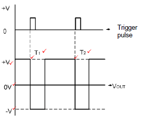 (7)
(7)
Note: Labelling of T1 and T2 is not critical. If only T1 or is labelled, award 2 marks.
7.9.3 t = 5RC ✓
= 5 x 12000 x 47 x 10-6✓
= 2,82 s ✓ (3)
7.10
 (3)
(3)
7.11 The differentiator is one type of op-amp where the magnitude of the output is determined by the rate ✓ at which the voltage applied to its input changes.✓
The differentiator is one type of op-amp where it changes a triangular wave into a square wave. (2)
7.12 Op-amps are packaged as an integrated circuit in a hard plastic body✓ with external pins for connections into circuits. ✓
Op-amps may also be packed in an SMD package. (2)
[50]
TOTAL: 200