MECHANICAL TECHNOLOGY GRADE 12 MEMORANDUM - NSC PAST PAPERS AND MEMOS NOVEMBER 2016
Share via Whatsapp Join our WhatsApp Group Join our Telegram GroupMECHANICAL TECHNOLOGY
GRADE 12
MEMORANDUM
NATIONAL SENIOR CERTIFICATE
NOVEMBER 2016
QUESTION 1: MULTIPLE-CHOICE QUESTIONS
1.1 A✓ (1)
1.2 A✓ (1)
1.3 C✓ (1)
1.4 C✓ (1)
1.5 B✓ (1)
1.6 C✓ (1)
1.7 D✓ (1)
1.8 C✓ (1)
1.9 A✓ (1)
1.10 C✓ (1)
1.11 C✓ (1)
1.12 B✓ (1)
1.13 C✓ (1)
1.14 D✓ (1)
1.15 C✓ (1)
1.16 C✓ (1)
1.17 C✓ (1)
1.18 D✓ (1)
1.19 A✓ (1)
1.20 C✓ (1)
[20]
QUESTION 2: SAFETY
2.1 Surface Grinder
- Do not force the work piece into the wheel. ✓
- Do not clean the machine while it is in motion. ✓
- Avoid large cuts. ✓
- Use coolant. ✓
- Know how to do an emergency stop. ✓
- Keep an eye on the position of the work piece. ✓
- Any coolant spilt on the floor must be clean immediately to prevent slipping. ✓
- Always stop the machine before taking measurements or adjusting the machine or work piece.
- Keep all tools clear of the worktable. ✓
- Do not allow the wheel to become badly glazed before dressing it. ✓
- Never operate the grinding machine at a speed higher than the recommended speed for a particular wheel. ✓
- Do not leave the machine while it is in operation. ✓
- Do not lean on the machine. ✓
Any 2 x 1 (2)
2.2 Arc welding
- Welding helmet ✓
- Gloves ✓
- Overall ✓
- Apron✓
- Boots ✓
- Leg protection ✓
- Ear protection ✓
- Vaporising mask. ✓
Any 2 x 1 (2)
2.3 Bearing puller
- Make sure that the legs of the puller are not worn. ✓
- Make certain that the legs are well secured. ✓
- Use split cover. ✓
- Do not work directly behind the puller. ✓
- Always keep an eye on the puller when tightening so that other components are not damaged in the process. ✓
- Use the right size of puller. ✓
- Puller must be 90° to the bearing. ✓
Any 2 x 1 (2)
2.4 3 mm✓ (1)
2.5 Rockwell tester
- The area around the tester should be cordoned off.✓
- Only one person inside the confined space.✓
- Wear protective clothing.✓
- Wear safety goggles.✓
- The hardness tester should be mounted on a rigid support on a work table.✓
- Specimen must be safely positioned. ✓
- Do not exceed the prescribed load. ✓
- Use the correct indenter.✓
- Specimen must be shielded. ✓
- Remove excess oil.✓
Any 3 x 1 (3)
[10]
QUESTION 3: TOOLS AND EQUIPMENT
3.1 Beam Bending Test
- To investigate the deflection of beams.✓
- To see if the beam is capable to support the load.✓
- To see if the beam is strong enough. ✓ (2)
3.2 CO reading (Gas Analyser)
- Rich mixture setting✓
- Incorrect idle speed✓
- Clogged air filter✓
- Faulty choke creating a rich mixture (jammed in the closed position.)✓
- Incorrect ignition timing. ✓
- Faulty injectors ✓
- Incorrect compression (rings and valves) ✓
- Too high float level ✓
Any 2 x 1 (2)
3.3 Advantages of MIG/MAGS welding
- Can weld in any position.✓
- Less skilled operator required.✓
- Long (continuous) welds can be made without stops and starts.✓
- Minimum post-weld cleaning/no slag removal is required.✓
- Cause less deformation.✓
- Gives better finish.✓
- Faster than arc welding.✓
- Less heat generated. ✓
- High deposition rate. ✓
Any 2 x 1 (2)
3.4 Multimeter
To test:
- DC voltage ✓
- DC current ✓
- AC current ✓
- AC voltage ✓
- Resistance✓
- Transistor✓
- Capacitor ✓
- Diode✓
- Battery(voltage) ✓
- Continuity ✓
- Temperature ✓
Any 2 x 1 (2)
3.5 Compression tester:
3.5.1 High tension lead
- The ignition system will be disabled✓
- To be able to remove spark plugs ✓
- Prevent electrical shock✓
- To protect the ECU
- Reduce fire hazard
Any 1 x 1 (1)
3.5.2 Fuel injectors disconnected
- To prevent unburned fuel entering the exhaust system.✓
- To prevent fuel entering the tester.✓
Any 1 x 1 (1)
3.5.3 Throttle valve fully open
- To obtain the correct amount of air entering the cylinder. ✓
- To obtain a correct reading.✓
Any 1 x 1 (1)
3.5.4 Recording the readings
- To compare the readings to the specification.✓
- To note the differences in readings between the cylinders.✓
Any 1 x 1 (1)
[12]
QUESTION 4: MATERIALS
4.1 Characteristics of cementite
- Hard ✓
- Brittle✓ (2)
4.2 Case hardening on camshaft
- To ensure hardness to the surface. ✓✓
- To ensure resistance against wear. ✓✓
- To ensure a soft and tough inside/core.✓✓
Any 1 x 2 (2)
4.3 Tempering hardened steel
- To reduce brittleness. ✓✓
- To increase toughness. ✓✓
Any 1 x 2 (2)
4.4 Iron carbon equilibrium diagram
 (7)
(7)
[13]
QUESTION 5: TERMINOLOGY
5.1 Gear calculation
5.1.1
Module = PCD
T
=90 ✓
30
= 3 ✓
(2)
5.1.2
OD =m(T+2)
= 3(90+2) ✓
= 276 mm ✓
(2)
5.1.3
PCD = m x T
= 3 x 90
= 270 mm
(2)
5.1.4
Dedenum = 1,25 x m or 1,157 x m
= 1,25 x 3 or 1,157 x 3 ✓
= 3,75 mm or 2,471mm ✓
(2)
5.1.5
Y = PCD A + PCDB ✓
2 2
= 270 + 90 ✓
2 2
= 135 + 45
= 180mm ✓
(3)
5.1.6
Indexing = 40
n
=40 ✓
33
=1 7 x 2
33 2
= 1 44 ✓
66
Indexing: = one full turn of the crank and 14 holes in a 66 hole plate✓ (3)
5.2 Key calculations
5.2.1
Width of key = Diameter
4
= 92 ✓
4
=23 mm ✓
(2)
5.2.2
Length of key = 1,5 x Diameter
= 1,5 x 92 ✓
= 15,33 mm ✓
(2)
5.2.3
Thickness of key = Diameter
6
= 92 ✓
6
= 15,33 mm ✓ (2)
5.2.4
T2 = T1 - 138 ✓✓
100
= 15,33 - 1,38 ✓
= 13,95 mm ✓
(4)
5.3 Milling Machine components
5.3.1 Functions of the index plate
- A plate with holes to be able to subdivide✓ 1 turn of the crank into fractions✓ of a turn. (2)
5.3.2 Function of the sector arms
- Used to ease ✓ the setting of the required number of holes✓
- Do not have to recount the number of holes needed. ✓ (2)
5.4 External V-screw thread
- Compound slide method ✓
- Cross slide method ✓ (2)
[30]
QUESTION 6: JOINING METHODS
6.1 Causes of welding defects
6.1.1 Undercutting
- Improper settings of equipment✓
- Welding speed too fast✓
- Current too high ✓
- Current too low ✓
- Arc length to long✓
- Incorrect electrode size ✓
Any 2 x 1 (2)
6.1.2 Lack of fusion
- Weld speed too fast✓
- Welding current too low✓
- Weld joint very wide✓
- Incorrect electrode size✓
Any 2 x 1 (2)
6.2 Ultrasonic test
- A high frequency sound wave ✓ is send into the metal✓
- The same unit ✓which used to send the sound wave is then used to receive✓the wave.
- The deflections✓in the wave received indicate defects✓ in the weld metal. (6)
6.3 Ultrasonic vs X-ray testing
- It can measure the depth of the defect.✓
- No additional material and equipment needed. ✓
- No isolation needed. ✓
- Safer than x-ray. ✓
- It is cheaper. ✓
Any 1 x 1 (1)
6.4 X-ray test on welded joint
- Photographic film/paper/plate ✓✓
- Monitor/TV/screen/computer✓✓ Any 1 x 2 (2)
6.5 Dye penetrant test
- To detect surface / external flaws on a welded joint.✓✓ (2)
6.6 Destructive tests
- Nick break test✓
- Bend test or Free bend test or Nick bend test ✓
- Machinability test✓
- Tensile test ✓
Any 2 x 1 (2)
6.7 MIG/MAGS shielding gases
- Argon ✓
- CO2✓
- Helium ✓
- Teral ✓
Any 2 x 1 (2)
6.8 MIG/MAGS welding
- Molten weld pool / welding joint / weld metal ✓
- Arc/Weld wire✓
- Contact nozzle / nozzle / contact tube ✓
- Gas shroud / welding pistol / nozzle ✓
- Shielding gas✓
- Earth cable/ earth / earth wire / earth clamp / ground wire / 'skelm'✓ (6)
[25]
QUESTION 7: FORCES
7.1 Resultant
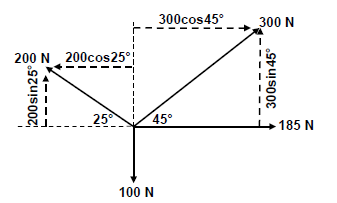
∑HC = 300cos45° - 200cos25°+185✓✓✓
= 212,13 - 181,26 + 185
= 215,87N✓
∑VC = 200sin25° - 100 + 300sin45° ✓✓✓
= 84,52 - 100 + 212,13
= 196,65N ✓
| Horizontal component | Magnitude | Vertical component | Magnitude |
| -200Cos25° ✓ | - 181,26 N | 200Sin25°✓ | 84,52 N |
| 300Cos45°✓ | 212,13 N | 300Sin45°✓ | 212,13 N |
| 185✓ | 185 N | 0 | 0 N |
| 0 | 0 N | -100 | - 100 N |
| TOTAL | 215,87 N ✓ | TOTAL | 196,65 N✓ |
R2 = HC2 +VC2
R = √215,872 + 196,652 ✓
R = 292,01N ✓
Tanθ = VC ✓
HC
= 196,65 ✓
215,87
θ = 42,33°
R = 292,01 N at 42,33° (42°20') north of east ✓
OR bearing 47,67° (47°40') East
7.2 Stress and Strain
7.2.1
 (5)
(5)
7.2.2 Strain
ε = σ ✓
E
ε = 20 x 106 ✓
90 x 109
= 0,22 x 10⁻³ ✓ (3)
7.2.3 Change in length
ε = Δl ✓
ol
Δl = ε x ol
= (0,22 x 10-3) x 0,3✓
= 0,07 x 10⁻³m
= 0,07 mm✓
(3)
7.3 Moments
Calculate A: Moments about B
ΣRHM = ΣLHM
(A x 8) + (300 x 2) = (550 x 6) + (800 x 3) ✓✓
8A = 3300 + 2400 - 600
8A = 8100
8 8
A = 637,5 N ✓
Calculate B: Moments about A
ΣLHM = ΣRHM
(B x 8) = (550 x 2) + (800 x 5) + (300 x 10) ✓✓
8B = 1100 + 4000 + 3000
8B = 8100
8 8
B = 1012,5 N ✓
ΣUpward = ΣDownward
637,5 + B = 300 + 550 + 800
B = 300 + 550 + 800 - 637,5
B = 1012,5N
(6)
[30]
QUESTION 8: MAINTENANCE
8.1 Effects – routine maintenance
- Risk of injury or even death.✓
- Financial loss due to damages.✓
- Decrease the lifespan of equipment. ✓
- Loss of valuable production time.✓ (3)
8.2 Preventive maintenance
- Planned/scheduled maintenance ✓
- Condition based maintenance ✓ (2)
8.3 Properties of oil
8.3.1 Pour point
Lowest temperature ✓at which a liquid remains pourable. ✓ (2)
8.3.2 Flashpoint
Lowest temperature✓ at which the oil gives off vapour which can ignite.✓(2)
8.4 Belt drive maintenance
- Wear and tear of the belts.✓✓
- The belts stretch.✓✓
- To ensure the belt stays in a good condition ✓✓
Any 1 x 2 (2)
8.5 Cutting fluid
- Cutting tool is kept cool. ✓✓
- Prolong life of a cutting tool. ✓✓
- Swarf / shavings/ cuttings are washed away. ✓✓
- Ensure a better finish. ✓✓
- Higher cutting or feed speed. ✓✓
- Increase productivity ✓✓
Any 1 x 2 (2)
8.6 Chain-drive maintenance
By doing the following regularly:
- Set the tension ✓✓
- Correct alignment✓✓
- Check for wear and tear ✓✓
- Clean system ✓✓
- Lubrication of parts ✓✓
Any 1 x 2 (2)
[15]
QUESTION 9: SYSTEMS AND CONTROL
9.1 Belt Drives
9.1.1 Rotation frequency of the driver pulley
V = πDn
n = V
πD
= 36
π(0,23)
= 49,82 r.s-1 x 60
= 2989,35r/min✓✓✓✓
(4)
9.1.2 Power transmitted
T1= 2,5
T2
T1 = 2,5 x T2
= 2,5 x 140
= 350 N
P = (T1 - T2)V
P= (350 - 140)x36
= 7560 Watt or 7,56 kW✓✓✓✓
(4)
9.2 Gear drives
9.2.1 Rotation frequency of the output shaft✓✓✓ (3)
(3)
9.2.2 Velocity Ratio
VR = NINPUT
NOUTPUT
= 1380
160
= 8,625 : 1
= 8,63:1✓✓
(2)
9.3 Hydraulics
9.3.1 Fluid pressure
AA = πDA2
4
= π0.042
4
= 1,26 x 10⁻³m2
PA = FA
AA
= 275 Pa
1,2566 x 10-3
= 218844 Pa
= 218,84 kPa✓✓✓✓
(4)
9.3.2 Load on piston B in kg
AB = πD2
4
= π0.0752
4
= 4,42 x 10⁻³
PB = FB
AB
FB = PB x AB
= (218,85 x 103) x (4,42 x 10-3)
= 967,32N
Mass = 967,32N
10
= 96,73kg✓✓✓✓
(4)
9.4 Traction control
Traction control system prevents ✓ the wheels from spinning. ✓ (2)
9.5 Air bags
- Driver and passengers do not ✓ need to activate ✓the air bags.
- It is automatically ✓ activated ✓
Any 1 x 2 (2)
[25]
QUESTION 10: TURBINES
10.1 Supercharger
- Roots ✓
- Twin screw ✓
- Centrifugal ✓
- Vane type ✓
Any 2 x 1 (2)
10.2 Supercharger function
- To improve the volumetric efficiency of an engine. ✓✓
- To make the car faster. ✓✓
- To increase the engine output / power. ✓✓
- Increase pressure in cylinder above atmospheric pressure. ✓✓
Any 1 x 2 (2)
10.3 Advantages of supercharger
- Supercharger has no turbo lag. ✓
- Supercharger is less expensive. ✓
- Supercharger is less complicated to mount. ✓
- Supercharger has less moving parts. ✓
- More efficient at lower revs. ✓
- No special shutdown procedure. ✓
Any 2 x 1 (2)
10.4 Turbocharger
By the exhaust gases. ✓ (1)
10.5 Runaway speed
The runaway speed of a water turbine is its speed at full flow ✓ and with no shaft load. ✓ (2)
10.6 Water turbines
10.6.1 Reaction principle ✓✓
OR
Francis ✓✓
OR
Description of operation:
Reaction turbines are acted on by water which changes pressure as it moves through the turbine and gives up its energy. The turbine must be encased to contain the water pressure or suction or the must be fully submerged in the water flow. ✓✓
Any 1 x 2 (2)
10.6.2 Impulse principle ✓✓
OR
Pelton ✓✓
OR
Description of operation:
The impulse turbine changes the velocity of the water jet. The jet pushes on the turbine’s curved blades which changes the direction of the flow. The resulting change in momentum (impulse) causes a force on the turbine blades. ✓✓
Any 1 x 2 (2)
10.6.3 Reaction principle ✓✓
OR
Kaplan ✓✓
OR
Description of operation:
Reaction turbines are acted on by water which changes pressure as it moves through the turbine and gives up its energy. The turbine must be encased to contain the water pressure or suction or the must be fully submerged in the water flow. ✓✓
Any 1 x 2 (2)
10.7 Gas turbine
- Intake / Inlet ✓
- Compression / Compressor ✓
- Combustion / Ignition ✓
- Exhaust / thrust / Outlet ✓
- Turbine / rotor / spinner ✓ (5)
[20]
TOTAL: 200