ENGINEERING GRAPHICS AND DESIGN PAPER 1 GRADE 12 QUESTIONS - NSC PAST PAPERS AND MEMOS NOVEMBER 2016
Share via Whatsapp Join our WhatsApp Group Join our Telegram GroupT6 ENGINEERING GRAPHICS AND DESIGN
PAPER 1
GRADE 12
NSC PAST PAPERS AND MEMOS
NOVEMBER 2016
INSTRUCTIONS AND INFORMATION
- This question paper consists of FOUR questions.
- Answer ALL the questions.
- ALL drawings are in first-angle orthographic projection, unless otherwise stated.
- ALL drawings must be completed using instruments, unless otherwise stated.
- ALL answers must be drawn accurately and neatly.
- ALL the questions must be answered on the QUESTION PAPER as instructed.
- ALL the pages, irrespective of whether the question was attempted or not, must be re-stapled in numerical sequence in the TOP LEFT-HAND CORNER ONLY.
- Proper planning is essential in order to complete all the questions.
- Print your examination number in the block provided on every page. 10. Any details or dimensions not given must be assumed in good proportion.
QUESTIONS
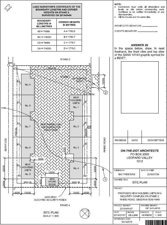
QUESTION 1: ANALYTICAL (CIVIL)
Given:
The site plan for proposed housing units in a security complex, a title panel and a table of questions. The drawing has not been prepared to the indicated scale.
Instructions:
Complete the table below by neatly answering the questions, which refer to the accompanying drawing and title panel. [30]
| QUESTIONS | ANSWERS | ||
| 1 | How many signatures are required? | 1 | |
| 2 | Who prepared the drawing? | 1 | |
| 3 | What scale is indicated for the drawing? | 1 | |
| 4 | Who checked the drawing? | 1 | |
| 5 | Who is responsible for the printing of the site plan? | 1 | |
| 6 | How many times has the drawing been revised? | 1 | |
| 7 | When was the site survey? | 1 | |
| 8 | How many rodding eyes are shown on the site plan? | 1 | |
| 9 | What does the abbreviation IC stand for? | 1 | |
| 10 | In what color should glass be indicated on a detailed drawing? | 1 | |
| 11 | Name the feature at 1. | 1 | |
| 12 | In what unit are the dimensions of the site plan? | 1 | |
| 13 | On what must the new paving be laid? | 1 | |
| 14 | What type of fence is proposed for the complex? | 2 | |
| 15 | What is indicated by the arrow at 2? | 1 | |
| 16 | Why would a residential stand not be allowed on the land immediately south-west of STAND 3? | 2 | |
| 17 | Referring to the building regulations, why would this proposed site plan not be approved? | 2 | |
| 18 | In the space below(ANSWER 18). determine the length of the electric security fence in meters. | 3 | |
| 19 | In the space below(ANSWER 19), determine the combined total are of ALL the proposed buildings in square meters. | 4 | |
| 20 | In the space in the title panel above (ANSWER 20), draw, in neat freehand, the front view and the top view of the SANS 10143 graphic symbol for a BIDET. | 3 | |
| TOTALS | 30 | ||
ANSWER 18 | ANSWER 19 SHOW ALL CALCULATIONS. |
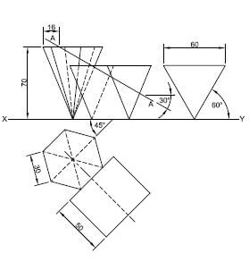
QUESTION 2: SOLID GEOMETRY
Given:
- The front view and the top view of a right regular hexagonal pyramid and a right equilateral triangular prism. The axes of both solids lie in a common vertical plane.
- An auxiliary view of the triangular prism
Specifications:
- The two solids do not touch.
- Both solids are cut by cutting plane AA.
Instructions:
Draw, to scale 1:1, the following views of the TWO solids:
2.1 The given front view
2.2 The sectional top view
2.3 The sectional right view
- Planning is essential.
- Show ALL necessary construction.
- Show ALL hidden detail on all three views. [37]
| ASSESMENT CRITERIA | |||
| 1 | CONSTRUCTION | 3 | |
| 2 | FRONT VIEW | 9 | |
| 3 | SECTIONAL TOP VIEW | 11 | |
| 4 | SECTIONAL RIGHT VIEW | 14 | |
| PENALTIES(-) | |||
| TOTAL | 37 | ||
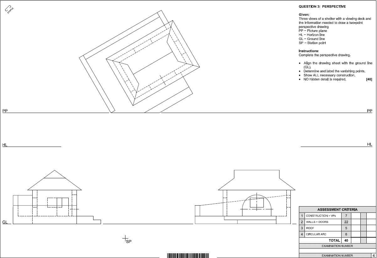
QUESTION 3: PERSPECTIVE
Given:
Three views of a shelter with a viewing deck and the information needed to draw a two-point perspective drawing
PP - Picture plane
HL - Horizon line
GL - Ground line
SP - Station point
Instructions:
Complete the perspective drawing.
- Align the drawing sheet with the ground line (GL).
- Determine and label the vanishing points.
- Show ALL necessary construction.
- NO hidden detail is required. [40]
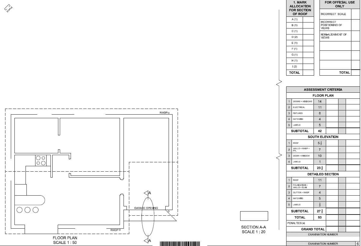
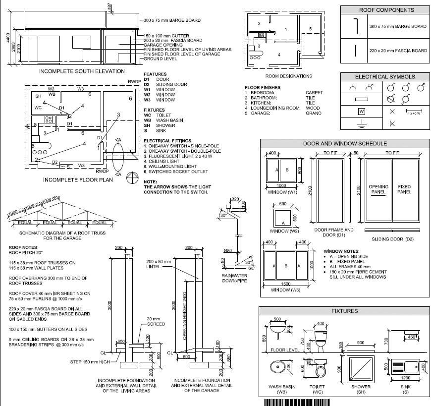
QUESTION 4: CIVIL DRAWING
Given:
- The incomplete south elevation of a new house, showing the walls, the door, window and garage openings, the roof and notes .
- The incomplete floor plan showing the walls, positions of the doors, windows, fixtures and the electrical layout
- A schematic diagram of a roof truss and roof notes
- The incomplete foundation and external wall details of the living areas and the garage
- Room designations and floor finishes
- The rainwater down-pipe
- A table of roof components
- A table of electrical symbols
- A door and window schedule
- A table of fixtures
- The incomplete floor plan of the new house, drawn to scale 1: 50, and the incomplete foundation and the break line of the detailed section, drawn to scale 1:20, on page 6
Instructions:
Answer this question BELOW: (4.1 -4.2)
4.1 Using the given incomplete floor plan, draw, in first-angle orthographic projection and to scale 1 : 50, the following views of the new house:
4.1.1 THE COMPLETE FLOOR PLAN Add the following features to the drawing:
- ALL doors and windows
- ALL fixtures as indicated by the abbreviations
- ALL electrical fittings as indicated by the numbers
- ALL hatching detail
4.1.2 THE COMPLETE SOUTH ELEVATION Show the following features on the drawing:
- The outside walls, door and window details and the garage opening
- The roof detail, including the fascia boards, barge boards, gutters and rainwater down-pipes
- The finished floor level
4.2 Using the incomplete foundation and break line on page 6,
draw, to scale 1:20, a DETAILED SECTION on cutting plane A-A of the area in the ellipse shown on the incomplete floor plan.
Show the following features on the drawing:
- The foundation, wall and garage opening detail
- The roof detail, including the fascia board and gutter
- ALL the external features of the new house to the left (west) of the ellipse
- ALL hatching detail. ONLY the substructure hatching may be drawn in neat freehand.
Label the following:
- The south elevation
- The room designations and floor finishes
- Ground level (use the correct abbreviation and show it on ALL the relevant views)
NOTE: ALL drawings must comply with the guidelines and graphical symbols contained in the SANS 10143. [93]