MECHANICAL TECHNOLOGY(FITTING AND MACHINING) GRADE 12 MEMORANDUM - NSC EXAMS PAST PAPERS AND MEMOS MAY/JUNE 2021
Share via Whatsapp Join our WhatsApp Group Join our Telegram GroupMECHANICAL TECHNOLOGY: FITTING AND MACHINING
GRADE 12
NATIONAL SENIOR CERTIFICATE EXAMINATION
MEMORANDUM
MAY/JUNE 2021
QUESTION 1: MULTIPLE-CHOICE QUESTIONS (GENERIC)
1.1 B ✓(1)
1.2 A ✓ (1)
1.3 C ✓ (1)
1.4 C ✓(1)
1.5 D✓ (1)
1.6 A ✓ (1)
[6]
QUESTION 2: SAFETY (GENERIC)
2.1 First aid basic treatment:
- Examination ✓
- Diagnosis ✓
- Treatment ✓ (3)
2.2 Drill press (Already been switched on):
- Never leave the drill unattended while in motion.✓
- Switch off the drill when leaving. ✓
- Use a brush or wooden rod to remove chips. ✓
- When reaching around a revolving drill, be careful that your clothes do not get caught in the drill or drill chuck. ✓
- Don't stop a revolving chuck with your hand. ✓
- Don't adjust the drill while working. ✓
- Don't open any guard while in motion. ✓
- Keep hands away from action points. ✓
- Do not force the drill bit into the material.✓
- Apply cutting fluid if required. ✓
(Any 2 x 1) (2)
2.3 Isolation of electrode holder:
To prevent electric shock. ✓ (1)
2.4 Disadvantages of the process layout:
- Production is not always continuous. ✓
- Transportation costs between process departments may be high. ✓
- Additional time is spent in testing and sorting as the product moves to the different departments. ✓
- Damage to fragile goods may result from extra handling. ✓
(Any 2 x 1) (2)
2.5 Advantages of the product layout:
- Handling of material is limited to a minimum.✓
- Time period of manufacturing cycle is less. ✓
- Production control is almost automatic. ✓
- Control over operations is easier. ✓
- Greater use of unskilled labour is possible. ✓
- Less total inspection is required. ✓
- Less total floor space is needed per unit of production. ✓
(Any 2 x 1) (2)
[10]
QUESTION 3: MATERIALS (GENERIC)
3.1 Heat-treatment:
- Heat the metal slowly to a certain temperature. ✓
- Soak the metal for a certain period to ensure a uniform temperature. ✓
- Cool the metal at a certain rate to room temperature. ✓ (3)
3.2 Quenching mediums:
- Water ✓
- Brine✓
- Liquid salts ✓
- Oil ✓
- Soluble oil and water ✓
- Sand ✓
- Molten lead ✓
- Air ✓
- Lime ✓
(Any 3 x 1) (3)
3.3 Annealing:
- To relieve internal stresses of the steel ✓
- Soften steel to make machining possible ✓
- Make steel ductile ✓
- Refine grain structure ✓
- Reduce brittleness ✓
(Any 1 x 1) (1)
3.4 Carbon steels:
- Low carbon steel ✓
- Medium carbon steel ✓
- High carbon steel ✓ (3)
3.5 Iron-carbon equilibrium diagram:
- Percentage carbon / carbon content ✓
- Temperature in °C ✓
- AC3 line / Higher critical temperature ✓
- AC1 line / Lower critical temperature ✓ (4)
[14]
QUESTION 4: MULTIPLE-CHOICE QUESTIONS (SPECIFIC)
4.1 B ✓ (1)
4.2 A ✓ (1)
4.3 B ✓ (1)
4.4 C ✓ (1)
4.5 D ✓ (1)
4.6 D ✓ (1)
4.7 C ✓ (1)
4.8 A ✓ (1)
4.9 B ✓ (1)
4.10 C ✓ (1)
4.11 B ✓ (1)
4.12 B ✓ (1)
4.13 A ✓ (1)
4.14 D ✓ (1)
[14]
QUESTION 5: TERMINOLOGY (LATHE AND MILLING MACHINE) (SPECIFIC)
5.1 Disadvantages of compound slide method:
- The automatic feed of the machine cannot be used.✓
- Causes poor finish. ✓
- Only short tapers can be cut. ✓
- It causes fatigue in the operator. ✓
(Any 3 x 1) (3)
5.2 Taper calculations:
5.2.1 Diameter of taper:
tan θ = D - d
2 2 x l
tan 10 = 165 - d
2 2 x 10
420 tan5º = 165 - d
d =165 - 36,75
d =128,25 mm (4)
5.2.2 Tailstock set-over:
x = L(D - d)
2 x l
x = 325(165 - 128,25)
2 x 210
x = 28,44 mm (3)
5.3 Calculation of parallel key:
5.3.1 Width = D/4
= 55/4
= 13,75 mm (2)
5.3.2 Thickness = D/6
= 55/6
= 9,17 mm (2)
5.3.3 Length = 1,5 diameterof shaft
= 1,5 x 55
= 82,5 mm (2)
5.4 Advantages of up-cut milling:
- Heavier cuts can be taken. ✓
- When hard steels are cut, the total cutting pressure is absorbed by the material at the back of the edge. ✓
- When milling material with a hard scale, the cut is started under the scale where material is softer, extending the life of the cutter✓
- A courser feed can be used. ✓
- The strain on the cutter and arbor is less. ✓
- Less vibration experienced on machine. ✓
(Any 2 x 1) (2)
[18]
QUESTION 6: TERMINOLOGY (INDEXING) (SPECIFIC)
6.1 Gear calculations:
6.1.1 Number of teeth:
Module = PCD
T
T = PCD
m
=136
4
= 34 teeth (2)
6.1.2 Dedendum:
Dedendum = 1,157(m) = 1,25(m)
= 1,157 x 4 OR = 1,25 x 4
= 4,63 mm = 5mm (2)
6.1.3 Outside diameter:
OD = PCD + 2(m) = m(T + 2)
= 136 + 2(4) OR = 4(34 + 2)
= 144 mm = 144 mm (2)
6.1.4 Circular pitch:
CP = m x π
= 4 x π
= 12.57mm (2)
6.2 Dove tail calculations:
w = 190 – 2(DE)
M = w + 2 (AC) + 2 (R) or M = w + 2 ( AC +R)
6.2.1 Minimum width of dove tail (w):
Calculate DE:
tan a = DE
AD
DE = ADtan a
= 38 tan30º
= 21,94mm
OR
tan θ = AD
ED
tan60º = 38
ED
ED = 38
tan60º
= 21,94 mm
w = 190 - 2(DE)
= 190 - 2(21,94)
= 190 - 43,88
= 146,12mm (6)
6.2.2 Distance over the rollers (M):
Calculate AC:
tan α = BC
AC
AC = BC
tan a
= 15
tan30º
= 25,98mm
M = w + 2(AC) + 2(R)
= 146,12 + 2(25,98) + 2(15)
= 146,12 + 51,96 + 30
= 228,08mm
OR
tan θ = CA
BC
CA = BCtanθ
= 15 tan60º
= 25,98 mm
M = w + 2(AC + R)
= 146,12 + 2(25,98) + 2(15)
= 146,12 + 81,96
= 228,08mm(6)
6.3 Milling of spur gear:
6.3.1 Indexing:
Indexing = 40/n
Indexing = 40/A
= 40/160
= ¼ x 6/6
= 6/24
Approximate indexing:
No full turns and 6 holes on a 24-hole circle ✓
OR
No full turns and 7 holes on a 28-hole circle ✓ (3)
6.3.2 Change gears:
D DR = (A - n) x 40/A
DDN
D DR = (160 - 163) x 40/160
DDN
= -3 x 40/160
=-120
160
= 3/4 x 8/8
D DR = 24/32
DDN (5)
[28]
QUESTION 7: TOOLS AND EQUIPMENT (SPECIFIC)
7.1 Reading:
Reading = 7,90 mm (2)
7.2 Brinell hardness test:
- Select the desired load to apply to the specimen. ✓
- The specimen is raised to be in contact with the Brinell ball by turning the hand wheel. ✓
- The load is then applied for about 15 - 30 seconds ✓
- Release the load from the specimen. ✓
- Measure the diameter of the impression.✓
- Determine the Brinell hardness number. ✓ (6)
7.3 The tensile tester:
- Yield stress ✓
- Ultimate / maximum tensile stress ✓
- Elongation percentage ✓
- Break stress ✓
- Limit of proportionality✓
- Elastic limit ✓
- Strain ✓
- Ductility ✓
(Any 3 x 1) (3)
7.4 Screw thread micrometer:
Identify:
7.4.1 Screw thread micrometer ✓ (1)
Function:
7.4.2 Measure the pitch diameter ✓ of a screw thread. (1)
[13]
QUESTION 8: FORCES (SPECIFIC)
8.1 Magnitude and direction of the equilibrant: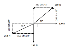
8.1.1 Sum of the horizontal components (HC):
ΣHC = 280cos45º + 120cos0º - 150cos90º - 250cos30º
= 197,99 + 120 - 0 - 216,51
= 101,48 Ν
OR
| Force | HC (x) | Total |
| 120 N | 120cos0º | 120N |
| 280 N | 280cos 45º | 197,99 N |
| 250 N | 250cos 210º | -216,51 N |
| 150 N | 150cos 270º | 0 N |
| Total: | 101,48 N |
(4)
8.1.2 Sum of the vertical components (VC):
ΣVC = 280sin45º + 120sin0º - 150sin90º 250sin30º
= 197,99 + 0 - 150 - 125
= -77,01 N
OR
| Force | HC (x) | Total |
| 120 N | 120cos0º | 120N |
| 280 N | 280cos 45º | 197,99 N |
| 250 N | 250cos 210º | -125 N |
| 150 N | 150cos 270º | -150 N |
| Total: | -77.01 N |
(4)
8.1.3 Magnitude of the equilibrium force:
E2 = VC2 + HC2
E = √(77,01)2 + (101.48)2
= 127,39 N (3)
8.1.4 Direction of the equilibrium force: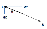
tanθ = VC
HC
tanθ = 77.01
101,48
θ = 37,19º
E = 127,39 N at 37,19° N of W (3)
8.2 Magnitudes of the reactions in supports A and B: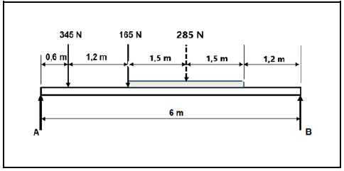
Calculate A:
Take moments about B:
ΣCWM = ΣACM
A x 6 = (285 x 2,7) + (165 x 4,2) + (345 x 5,4)
A x 6 = 769,5 + 693 + 1863
A x 6 = 3325,5
A = 3325,5
6
A = 554,25 N
Calculate B:
Take moments about A:
ΣCWM = ΣACM
(345 x 0,6) + (165 x 1,8) + (285 x 3,3) = 6 x B
207 + 297 + 940,5 = 6 x B
1444,5 = 6 x B
1444,5 = B
6
= 240,75 N = B (8)
8.3 Stress and Strain:
8.3.1 The resistance area of the bush:
A = π(D2 - d2)
4
A = π(0,0582 - 0,0422)
A =1,26 x 10⁻³ m2 (2)
8.3.2 The stress in the material:
σ = F/A
= 50 x 10 3
1,26 x 10-3
= 39682539,68 Pa
= 39,68 MPa (3)
8.3.3 Strain:
ε = Δl/l
= 0,975
68
= 14,34 x 10⁻³
(If any unit indicated, then NO mark for final answer) (3)
8.3.4 Young's modulus:
E = σ/ε
= 39,68 x 10⁶
14,34 x 10
= 2,77 x 10⁹ Pa
= 2,77 GPa (3)
[33]
QUESTION 9: MAINTENANCE (SPECIFIC)
9.1 Lack of preventative maintenance:
- Risk of injury or death. ✓
- Financial loss.✓
- Damage to parts.✓
- Loss of production time. ✓
(Any 2 x 1) (2)
9.2 Malfunctioning of chain drives:
- Uncovered chain drives not cleaned. ✓
- Tensioning device is not working efficiently.✓
- Chain is not inspected regularly for elongation. ✓
- Chain drive is not aligned. ✓
- Wear and tear of chain. ✓
- Wear of sprocket teeth.✓
- Lack of lubrication. ✓
- Chain drive has been overloaded. ✓
(Any 2 x 1) (2)
9.3 Wear on a gear drive system:
- Checking and replacement of lubrication levels. ✓
- Ensuring that gears are properly secured to shaft. ✓
- Cleaning and replacement of oil filter. ✓
- Reporting excessive noise, wear, vibration and overheating for expert attention. ✓
- Cleaning of gears regularly. ✓
(Any 2 x 1) (2)
9.4 Property of materials:
9.4.1 Polyvinyl chloride (PVC):
- Can be re-heated and re-shaped ✓
- Flexible ✓
- Rubber like substance and makes a dull sound when dropped.✓
- Can be modified to suit most applications. ✓
- Can be welded (plastic welding). ✓
- Can be bonded with an adhesive. ✓
- Weather resistant ✓
- Water proof ✓
- Easy to work with. ✓
- Light weight ✓
- Recyclable ✓
- Corrosion resistant ✓
(Any 2 x 1) (2)
9.4.2 Carbon fibre:
- Cannot be re-heated and re-shaped ✓
- Tough and strong material. ✓
- Light weight ✓
- Weather resistant✓
- Heat resistant✓
- Enhance strength of plastic by entrenchment✓
- Highly electrically conductive✓
(Any 2 x 1) (2)
9.4.3 Bakelite:
- Electrically non-conductor (electrical insulator) ✓
- Heat resistant ✓
- Well moulded into specific shapes ✓
- Weather resistant✓
- Cannot be re-heated and re-shaped ✓
(Any 2 x 1) (2)
9.5 Thermoplastic composites or thermo-hardened (thermosetting) composites:
9.5.1 Vesconite:
Thermoplastic ✓ (1)
9.5.2 Glass fibre:
Thermo-hardened/Thermosetting ✓ (1)
9.5.3 Carbon fibre:
Thermo-hardened/Thermosetting ✓ (1)
9.6 Uses of materials.
9.6.1 Teflon:
- Orthopaedic and prosthetic appliances✓
- Hearing aids ✓
- Joints✓
- Upholstery✓
- Mechanical parts (e.g., taps and bearings)✓
- Electrical insulation✓
- Non-stick coatings✓
(Any 1 x 1) (1)
9.6.2 Carbon fibre:
Sporting and leisure equipment like: Tennis rackets, squash rackets, badminton rackets, golf clubs, hockey sticks
- Model airplanes ✓
- Bicycle frames✓
- Ski’s✓
- Surf boards ✓
- Boat masts ✓
- Compressor blades✓
- Self- lubricating gears ✓
- Artificial satellites ✓
- Helicopter blades ✓
- Car bodies✓
- Airplane parts (fuselage) ✓
(Any 1 x 1) (1)
9.6.3 Nylon:
- Bushes ✓
- Gears ✓
- Pulleys ✓
- Fishing line✓
- Ropes ✓
(Any 1 x 1) (1)
[18]
QUESTION 10: JOINING METHODS (SPECIFIC)
10.1 Square Thread:
10.1.1 Mean diameter:
Pitch = Lead
Numberof starts
= 40/2
= 20 mm
Dm = OD - P/2
= 85 - 20/2
= 75 mm (4)
10.1.2 Helix angle of the thread:
tanθ = Lead
π x DM
= 40
π x 75
θ = tan-1(0,169765272)
= 9,63º or 9 38' (4)
10.1.3 Leading tool angle:
Leading tool angle = 90° -( helix + clearance angle)
= 90° -( 9,63° + 3)
= 77,37° or 77 22' (2)
10.1.4 Following tool angle:
Following tool angle = 90° +( helix angle - clearance angle)
= 90° +( 9,63° - 3°)
= 96,63° or 96 38' (2)
10.2 Screw thread label:
- Pitch diameter/mean/effective ✓
- Helix angle ✓
- Pitch / Lead ✓
- Root/Root length ✓ (4)
10.3 Uses of square thread:
- Vice screws ✓
- Brake screws ✓
- Lead screws of lathe machines ✓
- Scissor jacks✓
- Milling machine table feed screws ✓
- Hydraulic jacks (Adjustable top) ✓
(Any 2 x 1) (2)
[18]
QUESTION 11: SYSTEMS AND CONTROL (DRIVE SYSTEMS) (SPECIFIC)
11.1 Hydraulic calculations:
11.1.1 The fluid pressure in MPa:
Area:
AA = πD2A
4
= π(0.025)2
4
= 0,49 10 m OR 4,9 1 10 m
Pressure:
P = F/A
= 1,32 x 10 3
0,49 x 10-3
= 2,69 x 10⁶Pa
= 2,69 MPa (4)
11.1.2 The diameter of piston B:
PB = PA
FB = FA
AB AA
6,45 x 103 = 1,32 x 10³
AB 0,49 x 10⁻³
6,45 x 103 = 2,69 x 10⁶
AB
AB = 6,45 x 10³
2,69 x 10⁶
AB = 2,40 x 10⁻³
AB = πDB2
4
DB = √ 4AB
π
= √4(2,40 x 10⁻³)
π
= 0,05528m
= 55,28 mm (6)
11.2 Advantages of chain drive system over belt drive systems:
- No slipping or creep occurs. ✓
- Higher efficiency.✓
- Longer life span.✓
- Does not generate heat.✓
- Does not undergo the same degrading effects of what time has on belts.✓
- Much stronger✓
- Faster speeds can be obtained.✓
(Any 2 x 1) (2)
11.3 Functions of hydraulic reservoir:
- A fluid storage tank. ✓
- Promotes air separation from the fluid. ✓
- Support for the pump and electric motor. ✓
- Promotes heat dispersion. ✓
- Acts as a base plate for mounting control equipment.✓
- It allows for expansion or contraction of the hydraulic system. ✓
(Any 2 x 1) (2)
11.4 Application for hydraulic systems:
- Machine tools ✓
- Clutch systems ✓
- Brake systems ✓
- Aircraft ✓
- Jacks ✓
- Missiles ✓
- Ships✓
- Earth moving equipment ✓
- Punch machines ✓
- Turbines ✓
- Tractor lifts ✓
- Car lifts ✓
- Machine vices ✓
- Jaws of life ✓
- Trains ✓
(Any 1 x 1) (1)
11.5 Belt drive:
11.5.1 Rotational frequency:
NDR x DDR = NDN x DDN
NDR x 95 = 85 x 255
NDR = 85 x 255
95
NDR =228,16 r/min
OR
N = 3,8 r/sec (3)
11.5.2 Speed ratio:
Speed ratio = Diameter of driven pulley
Diameter of driver pulley
Speed ratio = 255
95
Speed ratio = 2,68 : 1
OR
Speed ratio = Frequency of driven pulley
Frequency of driver pulley
Speed ratio = 228
85
Speed ratio = 2,68 : 1 (3)
11.6 Gear drive:
11.6.1 Rotation frequency:
NA = Product of the numberof teeth on driven gears
NF Product of the numberof teeth on driving gears
NF = Product of the numberof teeth on driving gears
NA Product of the numberof teeth on driven gears
NF = TA x TC x TE x NA
TB x TD x TF
= 30 x 20 x 50 x 2500
40 x 60 x 70
= 446,43 r/min
OR
7,44 r/sec (4)
11.6.2 Gear ratio:
GearRatio = Product of the numberof teeth on driving gears
Product of the numberof teeth on driven gears
= 40 x 60 x 70
30 x 20 x 50
= 168000
30000
= 5,6 : 1
OR
Speed ratio = Ninoput
Noutput
= 2500
446,43
= 5,6:1 (3)
[28]
TOTAL: 200