Electrical Technology: Power Systems Questions - Grade 12 September 2021 Preparatory Exams
Share via Whatsapp Join our WhatsApp Group Join our Telegram GroupINSTRUCTIONS AND INFORMATION
- This question paper consists of SEVEN questions.
- Sketches and diagrams must be large, neat and FULLY LABELLED.
- Show ALL calculations and round off answer correctly to TWO decimal places.
- Number the answers correctly according to the numbering system used in this question paper.
- You may use a non-programmable calculator.
- Show the units for ALL answers of calculations.
- A formula sheet is provided at the end of this question paper.
- Write neatly and legibly.
QUESTIONS
QUESTION 1: MULTIPLE-CHOICE QUESTIONS
Various options are given as possible answers to the following questions. Choose the answer and write only the letter (A–D) next to the question numbers (1.1 to 1.15) in the ANSWER BOOK, for example 1.16 A.
1.1 To prevent infection when treating burns, the following should NOT be done:
- Do not take a pain killer
- Do not pop blisters
- Do not use a sterile gauze or bandage
- Do not hold the burned area under cool running water (1)
1.2 In a purely capacitive circuit, the relationship between the voltage and current is as follows:
- The current leads the voltage
- The current lags the voltage
- The current and voltage are in phase
- The current is zero (1)
1.3 During resonance the ...
- inductive reactance is greater than capacitive reactance.
- capacitive reactance is greater than inductive reactance.
- impedance is equal to 1.
- inductive reactance is equal to capacitive reactance. (1)
1.4 In a 240 V, 50 Hz RCL circuit with an inductance of 50 mH, the inductive reactance is equal to …
- 151,7 Ω.
- 151,7 H.
- 15,71 Ω.
- 15,71 H. (1)
1.5 The phase angle between the coils in a three-phase system is:
- 120°
- 180°
- 270°
- 90° (1)
1.6 Real power per phase is:
- The product of the current and the voltage
- The product of I sin ? and the voltage
- The product of I cos ? and the voltage
- The product of the resistance and the voltage (1)
1.7 A low power factor is usually caused by …
- the capacitive loads of a consumer.
- the inductive loads of a consumer.
- no load of a consumer.
- the resistive loads of a consumer. (1)
1.8 Transformers can operate when connected to …
- an AC supply only.
- a DC supply only.
- either an AC or a DC supply.
- a rectifier circuit. (1)
1.9 When operating three single phase transformers as a three-phase transformer, the following characteristic does not have to be identical:
- The frequency
- The voltage
- The current
- The colour (1)
1.10 In a forward-reverse starter, interlocking contacts are used to …
- keep the circuit energised after the start button has been released.
- show the operator which contactor is in operation.
- prevent the other contactor being energised while the motor is running in one direction.
- switch the power off when excessive currents occur (1)
1.11 The readings for an insulation resistance test between windings should be:
- At least 100 Ω
- At least 1M Ω
- At least 500 Ω
- None of the above-mentioned (1)
1.12 The direction of rotation of a three-phase motor is reversed by …
- changing the voltage.
- changing the load.
- changing the size of the conductors used.
- swopping any two of the three supply lines. (1)
1.13 A PLC is an …
- industrial computer that is programmed to perform a number of tasks in a strict order.
- industrial starter used to operate relays.
- industrial appliance which reads outputs to control inputs.
- industrial switch that works with electromagnetism. (1)
1.14 An opto-isolator is a semiconductor device that uses …
- heat to transfer an electrical signal between circuits.
- sound to transfer an electrical signal between circuits.
- light to transfer an electrical signal between circuits.
- electromagnetism to transfer an electrical signal between circuits. (1)
1.15 The following step is part of the PLC’s scan cycle:
- Barcode scan
- Process scan
- Voltage scan
- Frequency scan (1)
[15]
QUESTION 2: OCCUPATIONAL HEALTH AND SAFETY
2.1 Give the meaning of the following with reference to the Occupational Health and Safety Act, 1993 (Act 85 of 1993).
2.1.1 Risk (1)
2.1.2 Safe (1)
2.2 Explain the difference between quantitative risk analysis and qualitative risk analysis.(5)
2.3 State ONE example of a dangerous practice in an electrical workshop. (1)
2.4 Explain how inadequate lighting is an unsafe condition. (2)
[10]
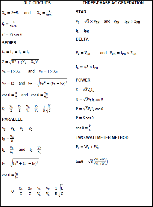
QUESTION 3: RLC CIRCUITS
3.1 Draw a neat, labelled characteristic curve showing the relationship between the inductive reactance and the frequency in a pure inductive circuit. (2)
3.2 State the relationship between the capacitive reactance and the frequency in a pure capacitive circuit. (1)
3.3 Define the term phase angle with reference to RLC circuits. (2)
3.4 FIGURE 3.4 below shows the phasor diagram of the voltages and current in a series circuit. Answer the questions that follow.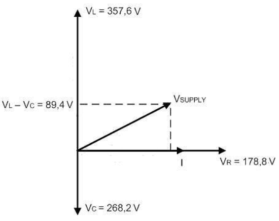
FIGURE 3.4
3.4.1 State with reference to the current, whether the phase angle is leading or lagging. (1)
3.4.2 Calculate the value of the supply voltage. (3)
3.4.3 Explain when the current would be in phase with the voltage of the circuit. (2)
3.5 State where resonant circuits are used. (1)
3.6 Describe the differences between the characteristics of series and parallel resonance. (2)
3.7 The series RLC circuit in FIGURE 3.5 consists of a 22 Ω resistor, an inductor of 50 mH and a capacitor with a reactance of 42,44 Ω. The series combination is connected to a 110 V/50 Hz supply. Answer the questions that follow.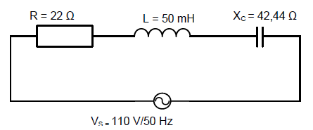
FIGURE 3.5
Given:
- R = 22 Ω
- L = 50 Mh
- X? = 42,44 Ω
- VS = 110 V
- f = 50 Hz
Calculate:
3.7.1 The inductive reactance (3)
3.7.2 The impedance of the circuit (3)
3.7.3 The value of the capacitor in the circuit in micro-farad (4)
3.8 Refer to FIGURE 3.8 below and answer the questions that follow.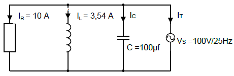
FIGURE 3.8
Given:
- IR = 10 A
- IL = 3,54 A
- C = 100 µF
- VS = 100 V
- f = 25 Hz
Calculate:
3.8.1 The current flowing through the capacitor (5)
3.8.2 The total current flowing through the circuit (3)
3.8.3 The phase angle (3)
[35]
QUESTION 4: THREE-PHASE AC GENERATION
4.1 State why the conductors of overhead transmission lines are made of aluminium and steel. (2)
4.2 Name the device that is used to measure the electrical energy consumed by a residence or business. (1)
4.3 Give THREE disadvantages a low power factor has for the consumer of electricity. (3)
4.4 Refer to FIGURE 4.4 below and answer the questions that follow.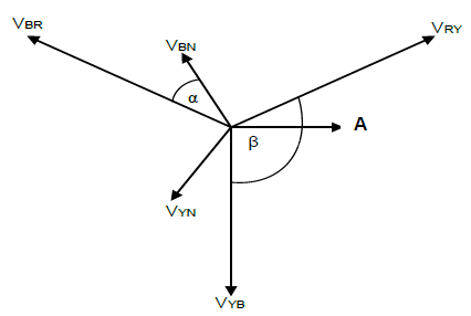
FIGURE 4.4
4.4.1 Identify the diagram shown in FIGURE 4.4. (1)
4.4.2 Write down the values of the angles α and β. (2)
4.4.3 Label the part A as shown in the diagram. (1)
4.4.4 Explain how the neutral is created in this system. (1)
4.4.5 Determine the value of VYB if VYN = 219,395 V (3)
4.5 A three-phase star connected system has a phase voltage of 220 V. The system has a rated power of 12 kW at a power factor of 0,87. The efficiency of the system is 86%.
Given:
- VPH = 220 V
- POUT = 12 kW
- cos ? = 0,87
 = 86%
= 86%
Calculate:
4.5.1 The line voltage (3)
4.5.2 The input power (3)
4.5.3 The line current (3)
4.6 A three-phase system with an apparent power of 30 kVA has a line and a phase voltage of 400 V. The system draws a current of 43,3 A and the lagging power factor causes a phase angle of 25°.
Given:
- S = 30 kVA
- VL = 400 V
- VPH = 400 V
- IL = 43,3 A
- ? = 25°
Calculate:
4.6.1 The real power (3)
4.6.2 The reactive power (3)
4.6.3 The phase current (3)
4.6.4 The power factor (3)
[35]
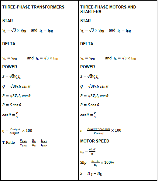
QUESTION 5: THREE-PHASE TRANSFORMERS
5.1 Name ONE application of the following:
5.1.1 Star-delta transformers (1)
5.1.2 Delta-star transformers (1)
5.2 State how the oil used in transformers can contribute to excessive heating. (2)
5.3 Describe the construction of a three-phase shell type transformer. (3)
5.4 Name TWO of the most common internal failures of three-phase transformers. (2)
5.5 A 50 kVA three-phase transformer has copper losses of 250 W and core losses of 180 W. The system operates at a power factor of 0,8.
Given:
- S = 50 kVA
- copper losses = 250 W
- core losses = 180 W
- cos ? = 0,8
Calculate:
5.5.1 The output power (3)
5.5.2 The efficiency of the transformer (3)
5.6 A three-phase delta-star transformer has a primary line voltage of 11 kV and delivers an output power of 25 kW at a power factor of 0,8. The turns ratio is 44 : 1.
Given:
- VLP = 11 kV
- POUT = 25 kW
- cos ? = 0,8
- Turns ratio = 44 : 1
Calculate:
5.6.1 The secondary phase voltage (4)
5.6.2 The secondary line voltage (3)
5.6.3 The secondary line current (3)
5.6.4 The secondary phase current (2)
5.6.5 The rating of the transformer (3)
[30]
QUESTION 6: THREE-PHASE MOTORS AND STARTERS
6.1 FIGURE 6.1 below shows a block diagram of the power transfer in an induction motor. Answer the questions that follow.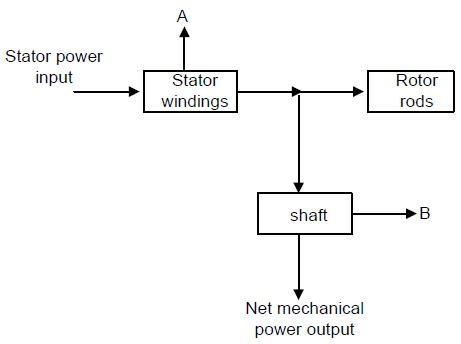
FIGURE 6.1: BLOCK DIAGRAM OF THE POWER TRANSFER IN AN INDUCTION MOTOR
6.1.1 Name the losses that occur at A and B. (2)
6.1.2 State THREE other parts a three-phase motor consists of, that are not shown in the block diagram above. (3)
6.2 Write down the name given to the difference between the rotor speed and the rotating magnetic field of the stator. (1)
6.3 Redraw the terminal box below in your ANSWER BOOK, then show the box connected in delta to the supply.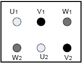 (3)
(3)
6.4 Describe the operation of the star-delta starter control circuit. (6)
6.5 Draw a neatly labelled circuit diagram of the control circuit of a three-phase forward-reverse starter. The contactors are rated at 220 V. (11)
6.6 A three-phase motor with two pole pairs per phase is connected to a 380 V supply. The rotor speed is 1 440 rpm and the synchronous speed is
1 500 rpm. The output power at a power factor of 0,85 is 5 kW.
Given:
- ? = 2
- V = 380 V
- NR = 1 440 rpm
- NS = 1 500 rpm
- cos ? = 0,85
- POUT = 5 Kw
Calculate:
6.6.1 The slip in rpm (3)
6.6.2 The frequency of the supply (3)
6.6.3 The line current at the rated output power (3)
[35]
QUESTION 7: PROGRAMMABLE LOGIC CONTROLLERS (PLC’s)
7.1 Define the following terms with reference to PLCs:
7.1.1 Hard wiring (1)
7.1.2 Scan time (2)
7.2 Draw a neatly labelled sketch showing the principle of a photo-transistor. (5)
7.3 Answer the following questions with reference to the OR logic gate.
7.3.1 Draw the logic symbol for this gate. (2)
7.3.2 Complete the truth table in FIGURE 7.3.2 below by ONLY writing the state of the output next to the letter in the ANSWER BOOK, for example e – 1.
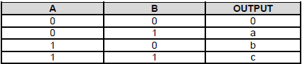 (3)
(3)
FIGURE 7.3.2: TRUTH TABLE
7.3.3 Draw the ladder diagram that represents this gate. (3)
7.4 State TWO examples of each of the following with reference to PLCs:
7.4.1 Input devices (2)
7.4.2 Output devices (2)
7.5 Refer to the FIGURE 7.5 below and answer the questions that follow.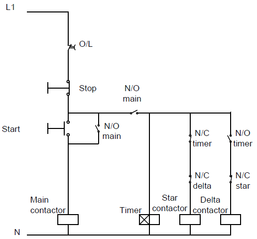
FIGURE 7.5
7.5.1 Draw a labelled ladder logic diagram of the circuit. (12)
7.5.2 Explain the function of the two normally closed contacts connected in series with the star and delta contactors. (2)
7.5.3 Explain why the circuit remains energised after the start button is released. (2)
7.5.4 Describe the function of the timer in the circuit. (1)
7.6 Draw a labelled block diagram showing a variable speed drive connected to a three-phase motor. (3)
[40]
TOTAL: 200
FORMULA SHEET