Electrical Technology: Power Systems Memorandum - Grade 12 September 2021 Preparatory Exams
Share via Whatsapp Join our WhatsApp Group Join our Telegram GroupINSTRUCTIONS TO MARKERS
- All questions with multiple answers imply that any relevant, acceptable answer should be considered.
- Calculations
2.1 All calculations must show the formulae.
2.2 Substitution of values must be done correctly.
2.3 All answers MUST contain the correct unit to be considered.
2.4 Alternative methods must be considered, provided that the correct answer is obtained.
2.5 Where an incorrect answer could be carried over to the next step, the first answer will be deemed incorrect. However, should the incorrect answer be carried over correctly, the marker has to re-calculate the values, using the incorrect answer from the first calculation. If correctly used, the candidate should receive the full marks for subsequent calculations.
2.6 Markers should consider that learners answers may deviate slightly from the marking guideline depending on how and where in the calculation rounding off was used. - These marking guidelines are only a guide with model answers.
- Alternative interpretations must be considered and marked on merit. However, this principle should be applied consistently throughout the marking session at ALL marking centres.
MEMORANDUM
QUESTION 1: MULTIPLE-CHOICE QUESTIONS
1.1
1.1 B (1)
1.2 A (1)
1.3 D (1)
1.4 C (1)
1.5 A (1)
1.6 C (1)
1.7 B (1)
1.8 A (1)
1.9 D (1)
1.10 C (1)
1.11 B (1)
1.12 D (1)
1.13 A (1)
1.14 C (1)
1.15 B (1) [15]
QUESTION 2: OCCUPATIONAL HEALTH AND SAFETY
2.1
2.1.1 The probability that injury or damage will occur. (1)
2.1.2 Free from any hazard. (1)
2.2 In quantitative risk analysis an attempt is made to numerically determine the probabilities of various adverse events and the likely extent of losses if a particular event took place. Qualitative risk analysis defines the various threats determining the extent of vulnerabilities and devising counter measures should a risk occur. (5)
2.3
- Use or misuse of power tools.
- Incorrect use and handling of hand tools.
- Etching of printed circuit boards. (Any 1 x 1) (1)
2.4 Inadequate lighting leads to poor visibility, which could lead to dangerous situations or injuries.(2)
[10]
QUESTION 3: RLC CIRCUITS
3.1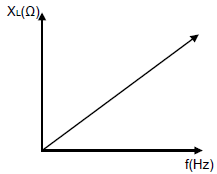
1 mark for correct labelling of axes
1 mark for correct shape of curve (2)
3.2 The capacitive reactance is inversely proportional to the frequency. (1)
3.3 It is the shift in phase between the supply voltage and the circuit current which results from the reactances and resistance in the circuit. (2)
3.4
3.4.1 The current lags the voltage. (1)
3.4.2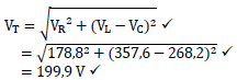 (3)
(3)
3.4.3 This occurs during resonance, when the voltage drop across the capacitor is equal to the voltage drop across the inductor. (2)
3.5 Used to tune radio and TV stations to a particular station. (1)
3.6
- In series, current is maximum and in parallel current is zero.
- In series, impedance is minimum and in parallel impedance is maximum. (2)
3.7
3.7.1
- X? = 2?ƒ?
= 2 × ? × 50 × 50 × 10−3
= 15,71 Ω (3)
3.7.2 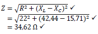 (3)
(3)
3.7.3
- XC = 1
2?fC
C = 1
2?fC
= 1
2×?×50×42,44
= 7,5 × 10⁻⁵F
= 75 µF (4)
3.8
3.8.1
- XC = 1
2?fC
= 1
2×?×25×100×10−6
= 63,66 Ω
IC = V
X?
= 100
63,66
= 1,57 A (5)
3.8.2 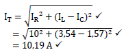 (3)
(3)
3.8.3
- cos ? = ??
??
? = cos−1 (??)
??
= cos−1 ( 10 )
10,19
= 11,08° (3)
[35]
QUESTION 4: THREE-PHASE AC GENERATION
4.1
- Aluminium is lighter and a good conductor.
- Steel adds strength. (2)
4.2 Kilowatt-hour meter (1)
4.3
- More current is used
- Higher monthly electricity bill
- More heat generated by equipment resulting in shorter lifespan
- More maintenance of equipment required (3)
4.4
4.4.1 Three-phase star connected system phasor diagram (1)
4.4.2
- α – 30°
- β – 120° (2)
4.4.3 A – VRN (1)
4.4.4 By connecting the common ends of three phasors together. (1)
4.4.5
- VYB = √3VYN
= √3 × 219,395
= 380 V (3)
4.5
4.5.1
- VL = √3VPH
= √3 × 220
= 381,05 V (3)
4.5.2
- η = POUT × 100%
PIN
PIN = POUT×100
η
= 12 000×100
86
= 13 953,49 W = 13,95 kW (3)
4.5.3
- PIN = √3VLIL cos ?
IL = PIN
√3VL cos ?
= 13 953,49
√3×381,05×0,87
= 24,30 A (3)
4.6
4.6.1
- ? = √3VLIL cos ?
= √3 × 400 × 43,3 × cos 25
= 27 188,44 W = 27,19 kW
OR
P = S cos ?
= 30 000 × cos 25
= 27 189,32 W = 27,19 kW (3)
4.6.2
- Q = √3VLIL sin ?
= √3 × 400 × 43,3 × sin 25
= 12 678,18 VAr = 12,68 kVAr
OR
? = ? sin ?
= 30 000 × sin 25
= 12 678,55 ??? = 12,68 ???? (3)
4.6.3
- IPH = IL
√3
= 43,3
√3
= 25 A (3)
4.6.4
- Power factor = cos ?
= cos 25
= 0,91 (3)
[35]
QUESTION 5: THREE-PHASE TRANSFORMERS
5.1
5.1.1 A step-down transformer in high voltage lines. (1)
5.1.2 As step-down transformers in distribution systems where a 4-wire system is required. (1)
5.2
- The oil may be impure due to carbonisation.
- The oil may be insufficient. (2)
5.3
- The windings are enclosed.
- The coils are wound around the centre section of the core.
- The axis of the shell-type can be vertical or horizontal. (3)
5.4
- Winding failures
- Tap changing failures
- Bushing failures
- Terminal board failures
- Core failures (Any 2 x 1) (2)
5.5
5.5.1
- POUT = S cos ?
= 50 000 × 0,8
= 40 000 W = 40 kW (3)
5.5.2
- η = ?0?? × 100%
?0??+??????
= 40000 × 100
40 000+250+180
= 98,94% (3)
5.6
5.6.1
- VLP = VPP = 110 00V
VPS = VPP
44
= 11 000
44
= 250 V (4)
5.6.2
- VLS = √3VPS
= √3 × 250
= 433,01 V (3)
5.6.3
- ? = √3VLSILS cos ?
ILS = P
√3VLS cos ?
= 25 000
√3×433,01×41,67
= 41,67 A (3)
5.6.4
- ILS = IPS
= 41,67 A (2)
5.6.5
- S = √3VLSILS
= √3 × 433,091 × 41,67
= 31 252, VA = 31,25 kVA
OR - ? = P
cos ?
= 25 000
0,8
= 1 250 VA = 1,25 kVA (3)
[30]
QUESTION 6: THREE-PHASE MOTORS AND STARTERS
6.1
6.1.1
- A – stator losses
- B – windage and friction losses (2)
6.1.2
- Terminal box
- Cooling fan
- End plates
- Yoke (frame)
- Bearings (Any 3 x 1) (3)
6.2 Slip (1)
6.3 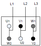
1 mark for each correct connection (3)
6.4
- When the start button is pressed, the main contactor (MC1) is energised. This changes the state of all MC1 contacts and the timer (T1) and the star contactor (MC2) are energised.
- The motor runs in star while the timer is timing and the delta contactor (MC3) is prevented from being energised.
- After the preset time, the timer de-energises the star contactor and energises the delta contactor.
- The motor runs in delta until the stop button is pressed. (6)
6.5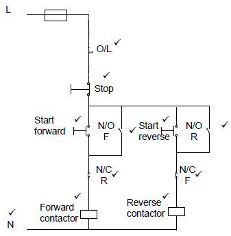
Symbol plus label = 1 mark
1 mark for connecting to neutral (11)
6.6
6.6.1
- ? = NS − NR
= 1 500 − 1 440
= 60 rpm (3)
6.6.2
- NS = f60
p
f = NSp
60
= 50 Hz (3)
6.6.3
- POUT = √3VLSILS cos ?
IL = POUT
√3VL cos ?
= 5 000
√3×380×0,85
= 8,94 A (3)
[35]
QUESTION 7: PROGRAMMABLE LOGIC CONTROLLERS (PLC’s)
7.1
7.1.1 When a device or socket has been wired up through a permanent, fixed circuit. (1)
7.1.2 The time the PLC takes to go through one complete cycle, processing each of the three steps.
7.2 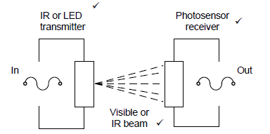
1 mark for in and out
1 mark for diagram correct (5)
7.3
7.3.1 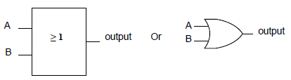
1 mark for symbol
1 mark for labels (2)
7.3.2
- a – 1
- b – 1
- c – 1 (3)
7.3.3 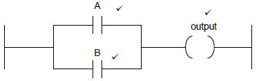 (3)
(3)
7.4
7.4.1
- Pushbutton switches
- Limit switches
- Proximity sensors
- Light sensors
- Temperature sensors (Any 2 x 1) (2)
7.4.2
- Relays
- Contactors
- Timers
- Lamps (Any 2 x 1) (2)
7.5
7.5.1 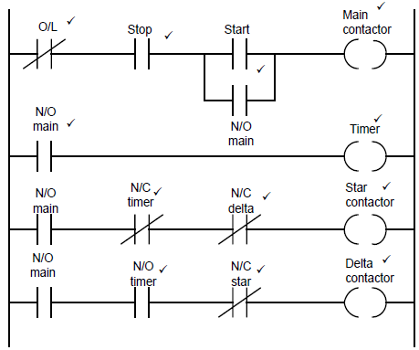 (12)
(12)
7.5.2 These are interlocking contacts, and they prevent one contactor from being energised while the other contactor is energised. (2)
7.5.3 The N/O main contact connected in parallel with the start button keeps the circuit energised (latching contact). (2)
7.5.4 The timer keeps the motor running in star for a preset time before energising the delta contactor. (1)
7.6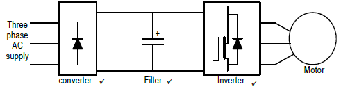
1 mark for each symbol and label correct (3)
[40]
TOTAL: 200