Mechanical Technology: Welding and Metalwork Memorandum - Grade 12 September 2021 Preparatory Exams
Share via Whatsapp Join our WhatsApp Group Join our Telegram GroupMEMORANDUM
SECTION A: COMPULSORY
QUESTION 1: MULTIPLE-CHOICE QUESTIONS
1.1 C
1.2 D
1.3 D
1.4 A
1.5 B
1.6 B (6 x 1) [6]
QUESTION 2: SAFETY (GENERIC)
2.1 Safety precautions
- Pressure gauges must be checked and tested regularly and adjusted or replaced if any malfunctioning occurs.
- Supporting pins that keep the platform at a desired height on the frame must be inspected for damage.
- Check the floor for oil and apparatus for leaks.
- The platform on which the workpiece rests must be rigid and square with the press cylinder. (Any 2 x 1) (2)
2.2 Product Layout![]() (2)
(2)
2.3 Perspex shield is installed to shield flying objects hurting the operator’s eye. (1)
2.4
2.4.1 Identification of machine Surface grinder (1)
2.4.2 Labels for parts of a surface grinder
- – Workpiece
- – Machine spindle
- – Magnetic table
- – Grinding wheel (4 x 1) (4)
[10]
QUESTION 3: MATERIALS (GENERICS)
3.1 Heat treatment refers to heating and cooling of metals under controlled conditions in their solid state so as to change their properties. (2)
3.2 HEAT TREATMENT PROCESS
PROCESS | PROPERTY | |
3.2.1 | Hardening | Very hard, maximum tensile and brittle |
3.2.2 | Tempering | Ductile |
3.2.3 | Annealing | Soft and ductile. |
3.2.4 | Normalising | Tough and machinable. |
(4 x 1) (4)
3.3 Purpose for case hardening:
- It hardens the surface.
- It provides a wear resistant surface.
- Strengthens core to withstand applied loads. (Any 2 x 1) (2)
3.4 Carbon effect:
- Steel with low carbon content will not respond very much to the hardening process. (2)
3.5
- Sound test workshop test on materials
- Bend test
- Filling test
- Machining test (Any 2 x 1) (2)
3.6 Reasons for annealing:
- To relieve internal stresses that may have been set up during other processes.
- To soften them to facilitate the machining processes.
- To make material ductile.
- Refine their grain structures.
- Reduce brittleness. (Any 2 x 1) (2)
[14]
QUESTION 4 MULTIPLE-CHOICE QUESTIONS (SPECIFIC)
4.1 D
4.2 C
4.3 B
4.4 D
4.5 A
4.6 C
4.7 B
4.8 B
4.9 A
4.10 B
4.11 D
4.12 D
4.13 B
4.14 D (14 x 1) [14]
QUESTION 5: MATERIALS TEMPLATES – ROLLING AND BENDING
5.1 Purpose of purlins in roof trusses:
- Purlins are fastened to the roof trusses to attach the roof covering. (2)
5.2 Reason why stiffeners are used in beams.
- To strengthen the web of the beam. (1)
5.3 The use of strip templates:
- They are used for longer sections of angle iron to mark off holes to be drilled. (1)
5.4 What does templates indicate?
- The correct form and measurements of the project
- The type of material to be used. (thickness and size)
- Job number
- Drawing number
- The number of components required
- This side up or other side up markings
- Coloured or shaped markings to denote hole diameters (Any 2 x 1) (2)
5.5 Labels of roof truss:
- A – Purlin
- B – Rafter
- C – Tie beam
- D – Shoe plate
- E – Inclined toe (5 x 1) (5)
5.6 Sketches:
5.6.1 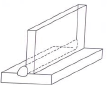 (3)
(3)
5.6.2 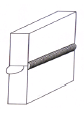 (3)
(3)
5.7 Calculations:
- Mean diameter = 220 + 220 + 12 ÷ 2
= 452 ÷ 2
= 226 mm (2) - Circumference = 3,142 x 226 mm
= 710,09 mm (1) - Length required for 2 straight pieces = 66 mm + 66 mm
= 132 mm - Length of material for 1 clamp = 710,09 mm + 132 mm
= 842,309 mm - Length of material for 20 clamps = 842,309 mm x 20
= 16 841 mm (3)
[23]
QUESTION 6: TOOLS
6.1 TWO different types of tap wrenches:
- T-handle or double handle OR
- Adjustable wrenches (2)
6.2 Uses of bench grinders:
- Grinding off excess material
- Cleaning surfaces with a wire wheel
- Polishing or buffing (Any 2 x 1) (2)
6.3 Purpose of a powersaw:
- It is used to rough cut large sections of metal. (1)
6.4 Determine the drilling speed of a pedestal drilling machine:
- Slower speed – for large diameters
- Faster speed – for small diameter holes. (2)
6.5 Reasons why guillotines have material thickness cutting limits:
- To preserve the shearing blades.
- Thicker or harder material will chip the brittle blade and result in poor future cuts or jamming of the guillotine. (2)
6.6 Sketch of basic AC arc welding machine: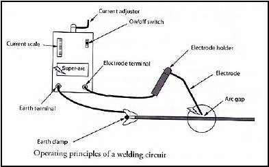
(Any 7 labels x 1) (7)
6.7 The use of shielding gas in MIG welding:
- MIG welding machines use a shielding gas to protect the weld pool from atmospheric gases. (2)
[18]
QUESTION 7: FORCES
7.1
7.1.1 Stress
- This is an internal force in material resisting a load. (2)
7.1.2 Strain
- This is the measurement of the deformation produced by the external forces and is determined by the ratio between deformation and original length. (2)
7.1.3 Safety factor
- This is the maximum number of times with which the maximum stress is decreased to obtain a safe stress. (2)
7.2
7.2.1 The stress in the material:
- Stress = Load
Area
but Area = πd2
4
= π × (0,05)2
4
1,964 × 10-3 m2
Stress = 50 × 103
1,964 × 10-3
= 25,46 × 10⁶ Pa
= 25,46MPa (4)
7.2.2 The strain if the final length of the bar is 3,00 m.
- Strain = ΔL
OL
but
Final length = OL + ΔL
ΔL = final length - OL
= 3,005 - 3
= 0,005 m
Strain = 0,005
3
= 1,67 ×10⁻³ (3)
7.3 Labelled sketch of the stress strain graph.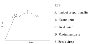
(Each label x 1) (7)
7.4
7.4.1 Calculate the reactions at the supports LR and RR
CALCULATING REACTIONS
- Take moments about RR
LR x 13 = (50 x 5 x 10,5) + (400 x 8) + (600 x 3)
= 2 625 + 3 200 + 1 800
LR = 586,5 N - Take moments about LR
RR x 13 = (600 x 10) + (400 x 5) + (50 x 5 x 2,5)
= 6000 + 2000 + 625
RR = 663,5 N (6)
7.4.2 Calculate the BM at each point of the beam A, B, C and D.
- BENDING MOMENTS
BMA: = 586,5 x 0 = 0 Nm
BMB: = (586,5 x 5) – (250 x 2,5) = 2307,5 Nm
BMC: = (586,5 x 10) – (250 x 7,5) – (400 x 5) = 1 990 Nm
BMD: = (586,5 x 13) – (250 x 10,5) – (400 x 8) – (600 x 3) = 0 m (4)
7.4.3 Calculate the shear force at A, B, C and D.
- SHEAR FORCE SFA: 586,5 N
SFB: 586,5 – 250 = 336,5 N
SFC: 586,5 – 250 – 400 = -64,5 N
SFD: 586,5 – 250 – 400 – 600 = -663,5 N (4)
7.5 Vector diagram: Scale 10 mm = 1 N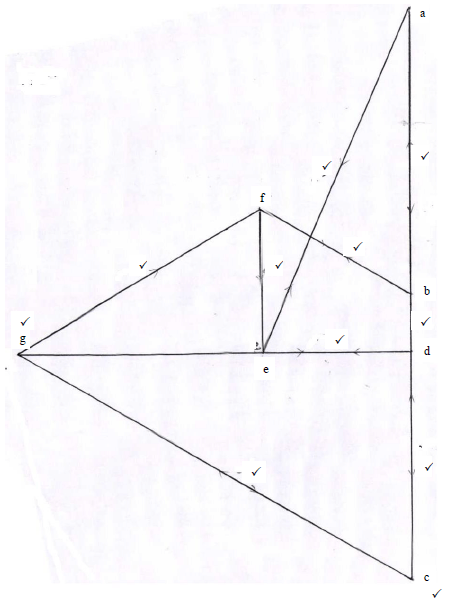
(11) [45]
QUESTION 8: JOINING METHODS (INSPECTION OF WELDS)
8.1 Internal defects – Nickbreak test:
- Slag inclusion
- Porosity
- Lack of fusion
- Oxidised metal
- Burned metal (Any 3 x 1) (3)
8.2 Visual requirements for an acceptable weld:
- Shape of the profile
- Uniformity of the surface
- Overlap
- Free from any external defects
- Penetration bead
- Root groove (Any 3 x 1) (3)
8.3 Elements during the visual inspection in welding:
- Shape of profile
- Uniformity of the surface
- Overlap
- Undercutting
- Penetration bead
- Root groove (Any 3 x 1) (3)
8.4 Performing an X-ray test on a welded joint:
- The X-ray or gamma ray source is placed in front of the object being tested.
- Once the tester is standing behind lead shields and far away from possible harmful exposure, the source is activated for a brief moment and the
X-rays penetrate the test piece. - As they pass through the areas of lower density (air pockets, cracks or inclusions) the rays expose the film as lighter on the negative, indicating a welding defect.
- Photographic films are useful because they provide a permanent record of the shadow which can be carefully studied. (5)
8.5 Factors that determine the current setting in arc welding.
- Base metal type
- Base metal thickness
- Electrode thickness (3 x 1) (3)
8.6 Factors that should be considered during oxyacetylene welding to ensure quality welding:
- Correct flame for the work at hand
- Correct angle of welding torch and rod
- Depth of fusion
- The welding rate (Any 3 x 1) (3)
8.7 Preventative measures for porosity during MIG welding:
- Cleaning the welding surface.
- Avoid rust in MIG wire electrode.
- Ensure that supply of shielding gas is not interrupted.
- Avoid welding in windy condition. (Any 3 x 1) (3)
[23]
QUESTION 9: JOINING METHODS (STRESSES AND DISTORTION)
9.1 Methods used to reduce distortion:
- Do not over-weld
- Apply intermittent welding
- Place welds near the neutral axis
- Use as few passes as possible
- Use back-step welding
- Anticipate the shrinkage forces
- Plan the welding sequence
- Use strongbacks
- Use clamps, jigs and fixtures (Any 5 x 1) (5)
9.2 Distortion on a welded joint:
- Weld distortion is the warping of the base plate caused by heat from the welding arc/flame. (2)
9.3 The meaning of shrinkage in a welded joint:
- Shrinkage is a form of plastic deformation where the metal has deformed because of contraction on cooling. (2)
9.4 The iron-carbon equilibrium diagram labels:
- – Ferrite and pearlite
- – Ferrite and austenite
- – Austenite
- – Cementite and austenite
- – Pearlite and cementite (5)
9.5 The factors that affect the grain size of steel when it is being cold worked:
- The prior amount of cold work.
- The temperature and time of the annealing process.
- The composition
- The melting point (4)
[18]
QUESTION 10: MAINTENANCE
10.1 Tagging plates have multiple holes:
- It has multiple holes so that more than one technician can lock out the machine simultaneously. (2)
10.2 General maintenance guidelines for a pedestal drilling machine :
- Visual checks of electrical wiring, switches, etc.
- Verify that all guards are secure and function correctly
- Ensure workspace is clear and without hindrances.
- Confirm availability and conditions of PPE
- Lubricate moving parts.
- Use moisture-penetrating oil spray to prevent rust.
- Check the availability of specific tools.
- Check the run-out of the spindle.
- Inspect belts for wear and tear.
- Ensure the drive belt is correctly tensioned.
- Check the condition of the rack and pinion mechanisms and lubricate.
- Ensure cuttings are removed.
- Inspect the Morse taper sleeves for burrs/scratches. (Any 2 x 1) (2)
10.3 Reasons for the maintenance of machines in the welding workshop:
- Promote cost saving.
- Improves safety.
- Increases equipment efficiency.
- Fewer equipment failure.
- Improves reliability of equipment. (Any 2 x 1) (2)
10.4 Methods to reduce friction when drilling holes:
- By reducing both drill speed and feed speed.
- By applying lubrication. (cutting fluid) (2)
[8]
QUESTION 11: TERMINOLOGY (DEVELOPMENT)
Calculations:
11.1
- 1 – 2 = ?? ?
12
= 3.142 × 72
12
1 – 2 = 18,849
1 – 2 = 2 – 3 = 3 – 4 = 18,849 (4)
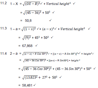
11.5
- a – x = 90 ÷ 2
= 45 (2)
[21]
TOTAL: 200