Mechanical Technology: Fitting and Machining Questions - Grade 12 September 2021 Preparatory Exams
Share via Whatsapp Join our WhatsApp Group Join our Telegram GroupINSTRUCTIONS AND INFORMATION
- Write your NAME and SURNAME on the ANSWER BOOK.
- Read ALL the questions carefully.
- Answer ALL the questions.
- Number the answers correctly according to the numbering system used in this question paper.
- Start EACH question on a NEW page.
- Show ALL calculations and units. Round off final answers to TWO decimal places.
- Candidates may use non-programmable scientific calculators and drawing instruments.
- The value of gravitational force should be taken as 10 m/s2.
- All dimensions are in millimetres, unless stated otherwise in the question.
- A formula sheet is attached to the question paper.
- Write neatly and legibly.
- Use the criteria below to assist you in managing your time.
QUESTION | CONTENT | MARKS | TIME IN MINUTES |
GENERIC | |||
1 | Multiple-choice questions | 6 | 6 |
2 | Safety | 10 | 10 |
3 | Materials | 14 | 10 |
SPECIFIC | |||
4 | Multiple-choice questions | 14 | 10 |
5 | Terminology (Lathe and Milling Machine) | 18 | 20 |
6 | Terminology (Indexing) | 28 | 25 |
7 | Tools and Equipment | 13 | 10 |
8 | Forces | 33 | 33 |
9 | Maintenance | 18 | 12 |
10 | Joining Methods | 18 | 12 |
11 | Systems and Control (Drive Systems) | 28 | 28 |
TOTAL: | 200 | 180 | |
QUESTIONS
QUESTION 1: MULTIPLE-CHOICE QUESTIONS (GENERIC) (COMPULSORY)
Various options are provided as possible answers to the following questions. Choose the correct answer and write only the letter (A–D) next to the question numbers (1.1–1.6) in the ANSWER BOOK, for example 1.7 A.
1.1 Which ONE of the following safety procedures is applicable to the maintenance/operation of a hydraulic press?
- Do not apply a wrench to revolving work.
- Guards could be removed when pressing soft material.
- Pressure gauges must be tested regularly and adjusted or replaced if any malfunctioning occurs.
- Use the machine table as an anvil. (1)
1.2 What is the best way of dealing with a hazard to ensure others are not put at risk?
- Remove it immediately
- Leave it for the supervisor to sort out
- Not placing a barrier tape around it
- Display a notice or warning sign (1)
1.3 Which of the following is a safety precaution related to a workbench?
- The tool rest must not be more than 3 mm from the grinding wheel.
- Make sure the chuck is correctly tightened.
- Stand on the side when switching on the machine.
- Keep rolling stock or items away from the bench end. (1)
1.4 What is the colour of an acetylene cylinder?
- Maroon
- Grey
- Green
- Black (1)
1.5 Starting devices on machinery are normally … in colour.
- red
- green
- black
- orange (1)
1.6 ONE of the following is NOT a safety device used in conjunction with guillotines.
- Self-adjusting guard
- Current scale
- Automatic sweep-away
- Electronic presence detection sensor (1)
[6]
QUESTION 2: SAFETY (GENERIC)
2.1 State TWO safety precautions that should be observed before pressing a bearing from a shaft using a hydraulic press. (2)
2.2 Sketch and label a product layout. (2)
2.3 What is the reason for mounting a Perspex shield on a bench grinding machine? (1)
2.4 Study both pictures in FIGURE 2.4 and answer the questions that follow.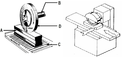
FIGURE 2.4
2.4.1 Name the machine shown in FIGURE 2.4. (1)
2.4.2 Identify the parts labelled A to D. (4)
[10]
QUESTION 3: MATERIALS (GENERIC)
3.1 Explain the term heat treatment. (2)
3.2 Tabulate the following heat treatment processes and identify ONE PROPERTY of each.
| PROCESS | PROPERTY |
| 3.2.1 Hardening | |
| 3.2.2 Tempering | |
| 3.2.3 Annealing | |
| 3.2.4 Normalising |
(4 x 1) (4)
3.3 Describe the specific purpose for case-hardening mild steel. (2)
3.4 What effect does carbon have when hardening steel? (2)
3.5 Name TWO workshop tests which are used to make a distinction between materials. (2)
3.6 State TWO reasons for annealing as a heat-treatment process. (2)
[14]
QUESTION 4: MULTIPLE-CHOICE QUESTIONS (SPECIFIC)
Various options are provided as possible answers to the following questions. Choose the correct answer and write only the letter (A–D) next to the question numbers (4.1–4.14) in the ANSWER BOOK, for example 4.17 A.
4.1 Which lathe operation is shown in FIGURE 4.1?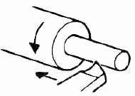
FIGURE 4.1
- Straight turning
- Internal parallel boring
- Thread cutting
- Reaming (1)
4.2 Identify the type of milling operation shown in FIGURE 4.2.
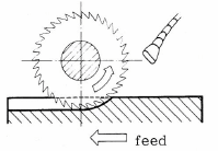
FIGURE 4.2
- Plain straight-tooth cutter
- Straight-tooth side-milling cutter
- Slitting saw
- Up-cutting milling (1)
4.3 Which ONE of the following lathe components must be engaged when you are cutting threads?
- Lead screw
- Feed shaft
- Cross slide dial
- Spindle-speed gear levers (1)
4.4 What does the abbreviation CNC stand for?
- Computer Numerical Control
- New Control Coding
- Company Numbers Control
- None of the above (1)
4.5 What is the deformation of a bar that is 0,73 m long when the strain is 0,5 x 10‾³?
- 0,365 mm
- 0,036 mm
- 0,653 mm
- 0,498 mm (1)
4.6 The main reason for performing a hardness test on engineering materials is to determine the …
- elasticity of the material.
- resistance of the material against denting
- corrosion of the material.
- fluidity of the metal. (1)
4.7 What does the symbol “D” denote in the Brinell hardness test shown in FIGURE 4.7?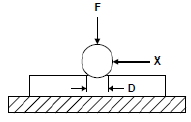
FIGURE 4.7
- Indentation diameter
- Hardness number
- Test piece
- Force applied (1)
4.8 Which ONE of the following is categorised as a mechanical drive?
- Screw drive
- Lead screw
- Gear drive
- White metal (1)
4.9 What will be the drill size for a M12 x 1,5 screw thread?
- 13,5 mm
- 1,5 mm
- 12 mm
- 10,5 mm (1)
4.10 A workpiece must have 13 gear teeth machined on its circumference. What type of indexing would you perform on this gear-blank?
- Angular indexing
- Simple indexing
- Rapid indexing
- New indexing (1)
4.11 If the module of a spur gear is 3 mm, what will be the addendum?
- 6
- 3
- 1,5
- 9 (1)
4.12 As shown in FIGURE 1.4, determine what the stress in a hollow pipe with a 50 mm outside diameter and a 30 mm inside diameter will be if a load of 80 N is applied.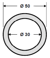
FIGURE 4.12
- 63,70 kPa
- 63,70 MPa
- 63,70 Pa
- 63,70 GPa (1)
4.13 There are different types of machine processes in manufacturing. Which process would you use to cut an internal thread of a hole?
- Tapping
- Boring
- Slotting
- Spot facing (1)
4.14 Identify the symbol, shown in FIGURE 4.14 below, which relates to a pneumatic system.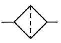
FIGURE 4.14
- Valve
- Filter
- Compressor
- Motor (1)
[14]
QUESTION 5: TERMINOLOGY (LATHE AND MILLING MACHINE) (SPECIFIC)
5.1 FIGURE 5.1 shows a tapered shaft which is to be turned to the dimensions given.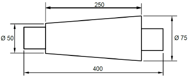
FIGURE 5.1
5.1.1 Calculate the amount of tailstock set-over. (2)
5.1.2 Calculate the included angle of the tapered portion in degrees and minutes. (3)
5.2 FIGURE 5.2 shows pictures of milling cutters.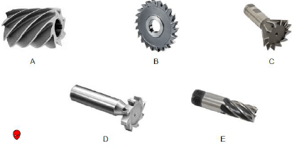
FIGURE 5.2
5.2.1 Name the milling cutters A–E. (5)
5.3 A circular shaft with an outside diameter of 85 mm must be machined with a two-start square thread of 12 mm pitch. Calculate the following:
5.3.1 The lead of the thread (1)
5.3.2 The mean diameter of the thread (2)
5.3.3 The helix angle of the thread (2)
5.4 FIGURE 5.4 below shows a drawing of a dividing head of a milling machine.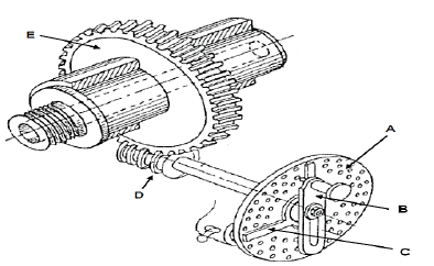
FIGURE 5.4
Explain the functions of parts A, D and E. (3)
[18]
QUESTION 6: TERMINOLOGY (INDEXING) (SPECIFIC)
6.1 Explain the following milling processes:
6.1.1 Gang milling (1)
6.1.2 Straddle milling (1)
6.2 Explain, step by step, the procedure to cut an external metric V-screw thread with a pitch of 2 mm on a centre lathe using the compound slide method. (5)
6.3 Define the term indexing as applied to milling processes. (1)
6.4 State the TWO milling methods. (2)
6.5 Calculate the differential indexing of a gear with 111 teeth. Hence determine:
6.5.1 The indexing required (Hint: Choose 120 divisions) (3)
6.5.2 The changed gears required for the dividing head (5)
6.5.3 What the meaning is of the positive (+) sign and the negative (-) sign for the change of gears (2)
6.6 The drawing in FIGURE 6.7 shows two precision rollers placed in an internal dovetail. Use the given information to answer the question that follows.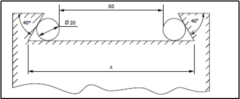
FIGURE 6.7
Calculate the measurement of the widest part (X) of the dovetail drawing. (6)
6.7 Name TWO common types of milling machines. (2)
[28]
QUESTION 7: TOOLS AND EQUIPMENT (SPECIFIC)
7.1 Explain how the following hardness tests are performed:
7.1.1 Brinell hardness tester (3)
7.1.2 Rockwell hardness tester (3)
7.2 Name the TWO ways in which hardness is measured. (2)
7.3 Study the screw thread micrometres shown in FIGURE 7.3.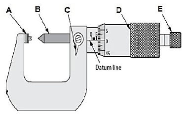
FIGURE 7.3
7.3 Label parts A–E. (5)
[13]
QUESTION 8: FORCES (SPECIFIC)
8.1 FIGURE 8.1 below shows a system of forces with four concurrent applied forces.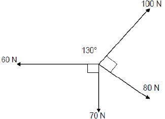
FIGURE 8.1
Calculate:
8.1.1 The sum of the horizontal components in magnitude and direction (2)
8.1.2 The sum of the vertical components in magnitude and direction (2)
8.1.3 The magnitude and direction of the resultant force and its equilibrant (5)
8.2 The diagram in FIGURE 8.2 below shows a beam with three vertically applied point loads of 5 kN, 8 kN and another 5 kN and also a 10 kN/m uniformly distributed load for a span of 4 m between supports B and C.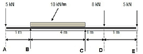
FIGURE 8.2
Calculate the magnitude of reactions RB and RC. (5)
8.3 A load of 40 kN is exerted on a brass bush used in a hydraulic press. The outer and inner diameters of the bush are 98 mm and 67 mm respectively. The original length of the bush is 80 mm and Young's modulus for brass is 90 GPa.
Calculate the:
8.3.1 Stress in the bush material (5)
8.3.2 Strain (3)
8.3.3 Change in length (3)
8.4 Draw and label the stress/strain diagram. (6)
8.5 What does the abbreviation FOS stand for in relation to stress calculations? (2)
[33]
QUESTION 9: MAINTENANCE (SPECIFIC)
9.1 Classify the following materials as either thermoplastic composites or thermo hardened (thermosetting) composites:
9.1.1 PVC (1)
9.1.2 Glass fibre (1)
9.1.3 Nylon (1)
9.2 Why is it essential to use a cutting fluid on a milling machine or centre lathe? State TWO reasons.(2)
9.3 How do you conduct preventative maintenance of gear system? State TWO. (2)
9.4 Give TWO reasons for using carbon fibre in the manufacture of bicycle frames. (2)
9.5 In tabulated form, compare ONE property and ONE use of the following plastic materials:
9.5.1 Teflon (2)
9.5.2 Vesconite (2)
9.5.3 Bakelite (2)
9.6 Name THREE factors that influence the coefficient of friction. (3)
[18]
QUESTION 10: JOINING METHODS (SPECIFIC)
10.1 A spur gear has 48 teeth and a module of 3. Determine, by means of calculations, the following:
10.1.1 The pitch-circle diameter (2)
10.1.2 The addendum (1)
10.1.3 The clearance (2)
10.1.4 The dedendum (2)
10.1.5 The outside diameter of the gear (2)
10.1.6 Circular pitch (1)
10.2 Draw a neat sketch of a metric square-screw thread. Indicate the following on the sketch:
10.2.1 Leading angle (1)
10.2.2 Following angle (1)
10.2.3 Clearence (1)
10.2.4 Helix angle (1)
10.3 Why would a multi-start thread be preferred mostly to a single-start thread? (2)
10.4 Describe what is meant by screw thread fit. (2)
[18]
QUESTION 11: SYSTEMS AND CONTROL (SPECIFIC)
11.1 Define rotational velocity of chains. (2)
11.2 A hydraulic system is used to lift a lathe. The specifications of the system are presented diagrammatically in FIGURE 11.2.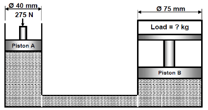
FIGURE 11.2
Calculate the following:
11.2.1 The fluid pressure in the hydraulic system when the system is in equilibrium (4)
11.2.2 Load in kilograms that can be lifted by piston B if a force of 275 N is exerted upon piston A (4)
11.2.3 State TWO applications of the system above. (2)
11.3 Define what is meant by hydraulics. (2)
11.4 A power saw’s motor has a pulley, 130 mm in diameter, that turns at 1 205 rpm. The speed at which the driven pulley drives the saw blades is 385 rpm. Calculate the diameter of the driven pulley. (2)
11.5 Make neat, freehand sketches of the ISO symbols representing the following pneumatic components:
11.5.1 Pump (2)
11.5.2 Air receiver (2)
11.5.3 Filter (2)
11.6 FIGURE 11.6 below shows a gear-drive system. Driver gear A on the shaft of the electric motor has 18 teeth that mesh with gear B with 36 teeth on a counter shaft. On the counter shaft is another driver gear, C, with 16 teeth that mesh with gear D with 46 teeth. The second counter shaft has driver gear E with 40 teeth, which drives gear F with 60 teeth on the output shaft.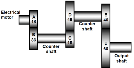
FIGURE 11.6
Calculate the:
11.6.1 Rotation frequency of the input shaft on the electric motor if the output shaft rotates at 160 r/min (3)
11.6.2 Velocity ratio between the input and output shaft (2)
11.6.3 In which direction will the driven shaft rotate if the driver gear rotates anti-clockwise? (1)
[28]
TOTAL: 200
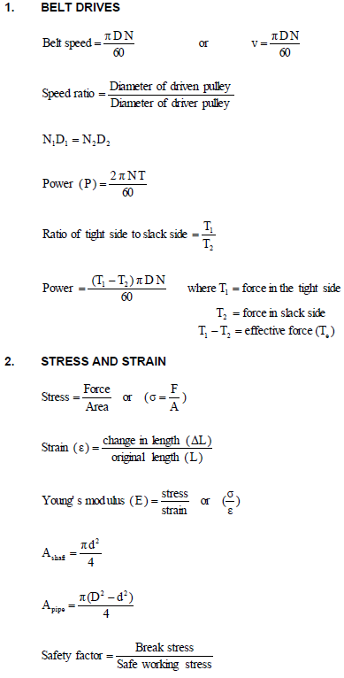
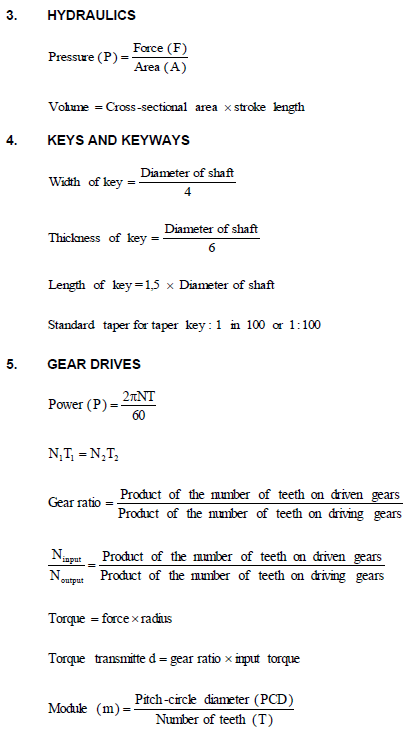
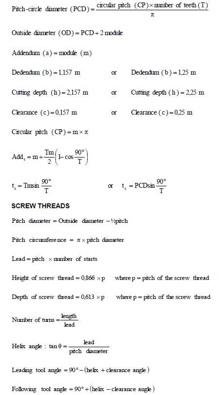
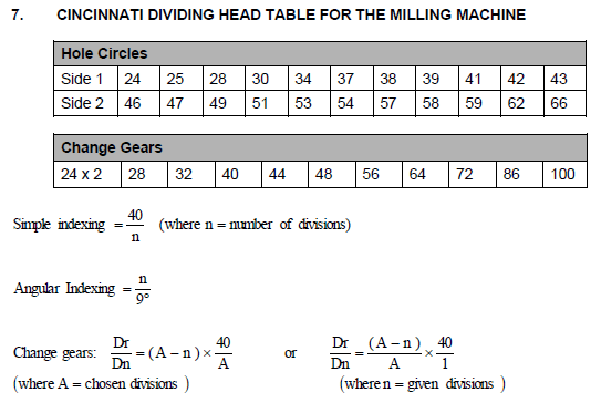
FORMULA SHEET FOR MECHANICAL TECHNOLOGY (FITTING AND MACHINING)