Mechanical Technology: Fitting and Machining Memorandum - Grade 12 September 2021 Preparatory Exams
Share via Whatsapp Join our WhatsApp Group Join our Telegram GroupMEMORANDUM
QUESTION 1: MULTIPLE-CHOICE QUESTIONS (GENERIC)
1.1 C
1.2 D
1.3 D
1.4 A
1.5 B
1.6 B (6 x 1) [6]
QUESTION 2: SAFETY (GENERIC)
2.1 Safety Precautions
- Pressure gauges must be checked and tested regularly and adjusted or replaced if any malfunctioning occurs.
- Supporting pins that keep the platform at a desired height on the frame must be inspected for damage.
- Check the floor for oil and apparatus for leaks.
- The platform on which the workpiece rests must be rigid and square with the press cylinder. (Any 2 x 1) (2)
2.2 Product layout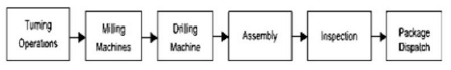 (2)
(2)
2.3 Perspex shield
- is installed to shield flying objects from harming the operator’s eye. (1)
2.4
2.4.1 Machine Identification
- Surface grinder (1)
2.4.2 Surface grinder parts label
- Workpiece
- Machine spindle
- Magnetic table
- Grinding wheel (4)
[10]
QUESTION 3: MATERIALS (GENERIC)
3.1 Heat treatment refers to heating and cooling of metals under controlled conditions in their solid state so as to change their properties.(2)
3.2 Heat treatment properties
| PROCESS | PROPERTY | |
| 3.2.1 | Hardening | Very hard, high tensile strength and brittle |
| 3.2.2 | Tempering | Tough, hard |
| 3.2.3 | Annealing | Soft, ductile, low tensile strength |
| 3.2.4 | Normalising | Tough and machinable |
(4)
3.3 Purpose of case-hardening
- It hardens the surface.
- It provides a wear resistant surface.
- Strengthens core to withstand applied loads. (Any 2 x 1) (2)
3.4 Carbon effect
- Steel with low carbon content will not respond very much to the hardening process.(2)
3.5 Workshop tests on materials
- Sound test
- Bend test
- Filing test
- Machining test (Any 2 x 1) (2)
3.6 Reasons for annealing
- To relieve internal stresses that may have been set up during other processes.
- To soften them in order to facilitate the machining processes.
- To make material ductile.
- Refine their grain structures.
- Reduce brittleness (Any 2 x 1) (2)
[14]
QUESTION 4: MULTIPLE-CHOICE QUESTIONS (SPECIFIC)
4.1 A
4.2 D
4.3 A
4.4 A
4.5 A
4.6 B
4.7 A
4.8 C
4.9 D
4.10 B
4.11 B
4.12 A
4.13 A
4.14 B (14 x 1) [14]
QUESTION 5: TERMINOLOGY (LATHE AND MILLING MACHINE) (SPECIFIC)
5.1 Lathe Taper turning
5.1.1
- Set-over = ?−? × ?????ℎ ?? ?????????
2 ?????ℎ ?? ?????
= (75-50)/2 x 400 / 250
= 12.5 x 1.6
= 20 mm (2)
5.1.2
- tan ? = ?.
2 ?
= 12.5 / 250
= 0.05
= tan−1 0.05 ? 2
Θ = 5.724° (3)
5.2 Milling Cutters.
5.2.1
- – Helical milling cutter
- – Side and face Cutter/ also Accept Staggered tooth cutter
- – Dovetail
- – T–Slot
- – End mill (5)
5.3 Cutting Square Threads
5.3.1 Lead = Pitch x Number of Starts
- = 2 x 12 = 24 mm (1)
5.3.2 Mean Diameter = OD – 0,5 Pitch
- = 85 – 0,5 x 12
= 91 mm (2)
5.3.3 Tan θ = Lead / π x Dm
- Tan θ = 24 / 91
Θ = 14,77 ° (2)
5.4 Dividing Head components
- A – Index plate: the aim of the index plate is to enable one revolution of the crank to be further subdivided into fractions of a revolution, especially where the fraction is not a factor of 40.
- D – Worm-shaft with a Single – start worm engages with a worm gear with 40 teeth.
- E – Worm wheel/gear obtain a rotary movement of the spindle. (3)
[18]
QUESTION 6: TERMINOLOGY (INDEXING) (SPECIFIC)
6.1 GEAR CALCULATIONS:
6.1.1 Gang Milling: Simultaneously using several cutters of different diameters and forms on the arbor, workpiece can be machined to size in one movement of the milling machine table. (1)
6.1.2 Straddle Milling: consists of two side and face cutters, separated by spacing collars of required dimensions to produce parallel work in one cut. (1)
6.2 Procedure to cut external metric V-screw thread using compound slide method
- Set up the workpiece in the centre lathe and turn the part to be threaded to the required diameter of the thread.
- Set the compound slide to 30º to the left of the centre line of that cross- slide and set the cutting tool up accurately in the tool post.
- Consult the index plate of the quick-change gear box and shift the levers accordingly for the necessary pitch of the screw thread.
- Start the centre lathe and set the cutting tool at touching point on the workpiece.
- Move the cutting tool a short distance off, to clear the end of the workpiece and feed the compound slide 0.05 mm inwards.
- With the centre lathe revolving, engage the half nuts at the correct line on the threading dial, putting the first cut of the screw thread in progress.
- Stop the centre lathe and check the screw thread pitch with a screw thread pitch gauge. (Any 5 x 1) (5)
6.3 Definition of Indexing is the process of evenly dividing the circumference of a circular work piece into equally spaced divisions, such as in cutting gear teeth, cutting splines, milling grooves in the reamers and taps. (1)
6.4 Milling methods
- Up-cut milling
- Down-cut milling (2)
6.5 Differential indexing
6.5.1 Indexing Required
- Indexing = 40
?
= 40/120
= 1 x 22
3 22
= 22/66
Indexing is 22 holes in a 66-hole circle (3)
6.5.2 Change of gears
- Gear ratio: ?????? = ?−? ? 40
?????? ? 1
= 120 −113 ? 40
120
= + 7 ? 8
3 8
= 56/24 - The driver gear has 56 teeth
- The driven gear has 24 teeth (5)
6.5.3
- The direction of motion is clockwise
- The crank handle will turn the same direction as index plate (2)
6.6 Dove tail Calculations
- Θ = 40°
α = 20° - x = r /(tan α)
= 10 /(tan 20)
= 27,47 mm - X = 80 + 2 R + 2 x
= 80 + 20 + (2 x 27,47)
= 154,949 mm (6)
6.7 Types of Milling machines
- Vertical milling machine
- Horizontal milling machine (2)
[28]
QUESTION 7: TOOLS AND EQUIPMENT (SPECIFIC)
7.1 Hardness Testers
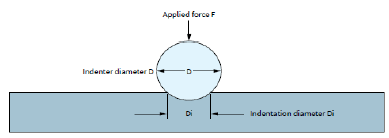
7.1.1 Brinell Hardness tester
- The Brinell Hardness Test involves indenting the test material with a piece hardened steel or carbide ball of 10 mm. The diameter of the indentation left in the test material is measured with a low-powered microscope.(3)

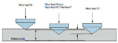
7.1.2 Rockwell Hardness tester
- Rockwell Hardness Test method involves indenting the test material with a diamond cone or hardened steel-ball indenter.(3)

7.2 Hardness measure of a metal.
- Resistance to penetration
- Elastic hardness
- Resistance to abrasion (Any 2 x 1) (2)
7.3 Screw thread micrometre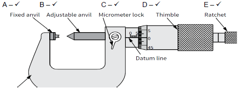 (5)
(5)
[13]
QUESTION 8: FORCES (SPECIFIC)
8.1 Resultant Force Calculations: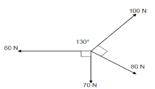
- Xcom = 100 cos 50 + 80 cos 40 - 60
= 65,56 N (2) - Ycom = 100sin 50 – 80 sin 40 - 70
= 95,18 N (2) - R = √(?2 + ?²)
R = 115.576 N
Tan θ = y/x
Tan Θ = 95.18/65.56
Θ = 55.44
= 55.44 °
Equilibrant = Resultant BUT IN THE OPPOSITE DIRECTION
Equilibrant = 115.567 N at 235.44 º (5)
8.2 Moments
- Converting the UDL to Point Load
4 x 10 = 40 kN @ 3 m from the left hand end
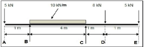
Calculation the Reactions by taking moments:
- CLOCKWISE MOMENTS = ANTICLOCK-WISE MOMENTS
(RC x 4) + (5 x 1) = (5 x 6) + (40 x 2) + (8 x 5)
Rc = 36,25 kN
(RB x 4) + (5 x 2) + (8 x 1) = (40 x 2) + (5 x 5)
RB = 21,75 kN (5)
8.3 Stress Calculations
8.3.1 Tensile Stress Calculations
F = 40 kN; D = 98, d = 67mm: L = 80 mm: E = 90 PGa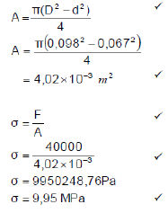 (5)
(5)
8.3.2 The Strain calculations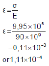 (3)
(3)
8.3.3 Change in length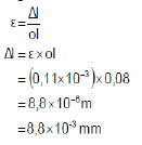 (3)
(3)
8.4 Stress/Strain diagram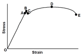
- – Limit of Proportionality
- – Elastic limit
- – Yield point
- – Maximum Force/Point
- – Point of Fracture (6)
8.5 FOS stands for Factor Of Safety or Safety Factor. (2)
[33]
QUESTION 9: MAINTENANCE
9.1 Material Classifications
9.1.1 PVC – Thermoplastic (1)
9.1.2 Glass fibre – Thermo-setting plastic (1)
9.1.3 Nylon – Thermoplastic (1)
9.2 Reasons for using cutting fluid when working on the centre lathe.
- It prolongs the life of a cutting tool.
- It prevents the shavings or metal chips from sticking and fusing to the cutting tool.
- It will carry away the heat generated by the turning process.
- It flushes away shavings/metal chips.
- It improves the quality of the finish of the turned surface. (Any 2 x 1) (2)
9.3 Gear Drives Maintenance.
- Checking and replenishment of lubrication levels
- Ensuring that gears are properly secured to shafts
- Cleaning and replacement of oil filters
- Reporting excessive noise and wear, vibrations and overheating for expect attention. (Any 2 x 1) (2)
9.4 Reasons for the use of carbon fibre
- It is light in weight.
- It is tougher and stronger.
- It can be bent to any shape when heated above 150 ºC. (Any 2 x 1) (2)
9.5 ONE property and ONE use of each composite
Composite | Property | Uses | |
9.5.1 | Teflon |
| Orthopaedic and prosthetic appliances, hearing aids, joints, upholstery, electric insulation and non-stick coating pans (Any 1) |
9.5.2 | Vesconite |
|
|
9.5.3 | Baskelite |
|
|
(6)
9.6
- Contact pressure
- Temperature
- Sliding velocity
- Type of a lubricant
- Surface roughness (Any 3 x 1) (3)
[18]
QUESTION 10: JOINING METHODS (SPECIFIC)
10.1 Square Thread Calculations: T = 48 mm ; m = 3
10.1.1
- PCD = T x m
= 48 x 3 = 144 mm (2)
10.1.2 Add = Module = 3 mm (1)
10.1.3
- Clearance = 0,157 x 3
= 0,471 mm (2)
10.1.4
- Ded = 1,157 x 3
= 3,471 mm (2)
10.1.5
- OD = PCD + 2 x 3
= 150 mm (2)
10.1.6
- Circular Pitch
= π x m
= π x 3 = 9,424 mm (1)
10.2 Left-hand square screw thread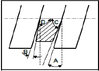
- – Leading Angle (1)
- – Following or Trailing Angle (1)
- – Clearance (1)
- – Helix angle (1)
10.3 A multi-start thread allows for a faster travel or movement and is more efficient as it loses less power through friction compared to single start thread. (2)
10.4 Screw Thread fit is a combination of allowances and tolerances and a measure of tightness or looseness between the bolt and nut. (2)
[18]
QUESTION 11: SYSTEMS AND CONTROL (DRIVE SYSTEMS) (SPECIFIC)
11.1 Rotational velocity is where a body rotates (spin) around its axis. It is the rotation rate or how fast a body revolves or turns. It is measured in radians
per second. (2)
11.2 Hydraulic system calculations
11.2.1 Calculate the Fluid pressure 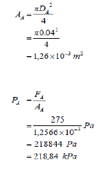 (4)
(4)
11.2.2 Load on the piston B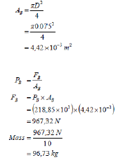 (4)
(4)
11.2.3 Hydraulic System Applications
- Machine tools, motor vehicle, hydraulic jacks (Any 2 x 1) (2)
11.3 Hydraulics refers to the transmission and control of forces and movement by means of fluid. Fluid (generally oil) is used to transmit energy. (2)
11.4 Belt Drive Calculations
- Nmotor x Dmotor = Nblade x Dblade
130 x 1205 = 385 x Dblade
Dblade = 406,883 pm (2)
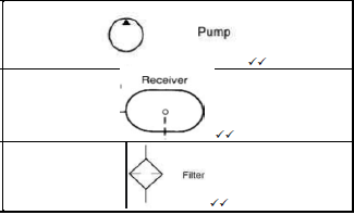
11.5 Pneumatic symbols
11.5.1 | Pump |
|
11.5.2 | Air receiver | |
11.5.3 | Filter |
11.6
11.6 Gear-Drive system calculations:
Data: (6)
11.6.1 Rotation speed of Electric motor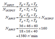 (3)
(3)
11.6.2 Velocity ratio
- VR = NINPUT
NOUTPUT
= 1380
160
= 8,625:1
- 863:1 (2)
11.6.3 Driven will rotate Clockwise (1)
[28]
TOTAL: 200