ELECTRICAL TECHNOLOGY GRADE 12 MEMORANDUM - NSC PAST PAPERS AND MEMOS FEBRUARY/MARCH 2017
Share via Whatsapp Join our WhatsApp Group Join our Telegram GroupELECTRICAL TECHNOLOGY
GRADE 12
NSC PAST PAPERS AND MEMOS
FEBRUARY/MARCH 2017
INSTRUCTIONS TO MARKERS
- All questions with multiple answers imply that any relevant, acceptable answer should be considered.
- Calculations:
2.1 All calculations must show the formula/e
2.2 Substitution of values must be done correctly
2.3 All answers MUST contain the correct unit to be considered
2.4 Alternative methods must be considered, provided that the same answer is obtained
2.5 Where an erroneous answer could be carried over to the next step, the first answer will be deemed incorrect. However, should the incorrect answer be carried over correctly, the marker has to re calculate the values, using the incorrect answer from the first calculation. If correctly used, the learner should receive the full marks for subsequent calculations - The memorandum is only a guide with model answers. Alternative interpretations must be considered, and marked on merit. However, this principle should be applied consistently throughout the marking session at ALL marking centres.
MEMORANDUM
QUESTION 1: OCCUPATIONAL HEALTH AND SAFETY
1.1
- Working on a live system with exposed conductors. ✔
- Working with portable electric equipment that is not insulated correctly. ✔
- Using electrical machines without using the required safety equipment or clothing. (2)
1.2
- An unsafe act is the performance of a task or other activity that is conducted in a manner that may threaten the health and/or safety of workers✔
- An unsafe condition is a condition in the work place that may cause property damage and or injury✔ (2)
1.3
- Do not touch the victim with your bare hands until the supply is turned off. ✔ Switch off the mains supply. ✔
- Call a teacher or medical person for help. ✔
- If the electricity cannot be switched off and the victim is still in contact with it push the wire away with an insulated object. ✔ (4)
- 1.4 No person may enter or remain in a workplace under the influence of drugs as he may place himself and other persons in danger✔ while operating machinery. ✔ (2)
[10]
QUESTION 2: THREE-PHASE AC GENERATION
2.1
2.1.1 The actual power consumed✔ by the load✔ (2)
2.1.2
- The power lost✔ in the form of heat✔
- The power lost to overcome the reactive component of the load (2)
2.2  (5)
(5)
2.3
2.3.1
IP = IL ✔
√3
= 30 ✔
√3
= 17,32 A ✔ (3)
2.3.2
Z = VP ✔
IP
= 380 ✔
17,32
= 21,93Ω ✔ (3)
2.3.3 If the power factor is improved, the load will draw less current✔ (1)
2.3.4 Cost saving as consumers use less current✔ (1)
2.4
PT = P1 + P2 ✔
= 100 + 250 ✔
= 350 W ✔ (3)
QUESTION 3:THREE-PHASE TRANSFORMERS
3.1 The purpose of the transformer is to step down or step up an AC voltage✔ (1)
3.2
- Air-cooled ✔
- Water-cooled ✔
- Oil-cooled (2)
3.3 Distribution system to the end consumer✔ (1)
3.4
3.4.1
ILS = S ✔
√3VLS
= 25000 ✔
√3 × 380
= 37,98 A ✔ (3)
3.4.2
ILP = S ✔
√3VLP
= 25000 ✔
√3 × 6000
= 2,40A ✔ (3)
3.4.3
IPh = IL ✔
√3
= 2,40 ✔
√3
= 1,38 A ✔ (3)
3.4.4
NP = IPh(S) ✔
NS IPh(P)
= 37,98 ✔
1,38
= 27,5 : 1
TR ≈ 27 : 1 ✔ (3)
3.5 It can serve both single phase✔ and three-phase loads✔ because of the availability of neutral point (2)
3.6
- Regular maintenance will maintain the efficiency of the transformer✔ and increase the lifespan of the transformer✔
- To identify and detect any abnormal function of the transformer (2)
[20]
QUESTION 4: THREE-PHASE MOTORS AND STARTERS
4.1
- They require less maintenance as they do not have as many parts as a single phase motor✔
- For the same size frame as a single phase motor they deliver a higher torque. (1)
4.2 If the rotor is not rotating freely and switched on it may cause extensive damage✔ to the motor or the operator may get injured ✔ (2)
4.3
- Check that all electrical connections are secure ✔
- Check the insulation resistance between windings ✔
- Check the insulation resistance between windings and earth (2)
4.4 Electrical connection would indicate that there is a short circuit between the rotor and stator✔ which is a fault condition which could cause damage to the motor. ✔ (2)
4.5
- Mechanical loses ✔
- I2R losses ✔
- Iron losses (2)
4.6
4.6.1
POUT (100) = S × cosθ ✔
= 15000 × 0.8 ✔
12000 W
12 kW ✔ (3)
4.6.2
POUT = POUT(100) × η ✔
= 12000 × 0,95 ✔
= 11,4 KW ✔ (3)
4.6.3
IL = S ✔
VL × √3
= 15000
√3 × 380
= 22,79 A ✔ (3)
4.7
4.7.1 More power will be available to do the work required of the motor✔ (1)
4.7.2
- If the power factor of the motor was improved the voltage would still remain constant✔ and the motor would still deliver the same power ✔but it would require less current to deliver the power✔ or the reactance power will decrease (3)
4.8
4.8.1
- The starter reduces the voltage across each phase✔ by connecting the motor in star ✔ VPH = VL
√3 - This reduction in voltage across each phase will reduce the current in each phase✔ (3)
4.8.2
- At start the motor draws more current than normal full load current✔ this can cause the motor to experience unnecessary tripping ✔as the protection will be set to close to full load current. Reducing the current at start reduces the unnecessary tripping. ✔ (3)
4.8.3
- The overload unit relay offers protection to the motor and operator ✔under fault conditions.✔ It will operate removing power from the motor making conditions safe.✔ (3)
4.8.4
- When connected in the star mode MC2 (N/C) contacts ✔which are N/C contacts on the star contactor✔ will be open as the star contactor is energized.✔ These contacts are in series with the delta contactor coil✔ so will prevent the coil from been energized when the motor is running in star.✔ (5)
4.9
- The frequency of the voltage and current supplied to the motor determines the speed at which induction motors will operate NS = f/p✔ this means that if the frequency changes so may the speed of induction motors operating✔ which may be problematic depending upon the function of the motor. ✔ (3)
4.10 The speed is indirectly proportional to the number of pole pairs. ✔ (1)
[40]
QUESTION 5: RLC
5.1
- Inductance of the inductor✔
- Applied frequency✔ (2)
5.2 An increase in the capacitance of a capacitor will result in a decrease in the capacitive reactance of a capacitor. ✔ (1)
5.3
- Resonance is when the capacitive reactance of a circuit is equal to the inductive reactance of a circuit✔
- The resistance is equal to the impedance and ✔ Ɵ = 0✔ (3)
5.4
5.4.1
XL = 2πfL ✔
= 2 × π × 50 × 400mH ✔
= 125,66 Ω ✔ (3)
5.4.2
XC = 1 ✔
2πfC
= 1 ✔
2 × π × 50 × 47 × 10-6
= 67,72 Ω ✔ (3)
5.4.3
Z = √ R2 + (XL - XC)2 ✔
= √ 202 + (125,66 - 67,72)2 ✔
= 61, 29 Ω ✔ (3)
5.4.4
Q = 1/R √L/C ✔
= 1 √400 × 10-3 ✔
20 7 × 10-6
= 4,61 ✔ (3)
5.5 The circuit is more inductive✔ because the inductive reactance is larger than the capacitive reactance✔ (2)
[20]
QUESTION 6: LOGIC
6.1 6.1.1 Programmable Logic Controller✔ (1)
6.1.2
- PLC control allows for easy quick change to be made to a system without having to do major rewire. ✔
- PLC programs can be stored electronically. ✔
- PLC control reduces components therefore reducing the size of control panels.
- Reduction in the components used reduces cost.
- Less/No moving parts depending on the type of PLC
- More reliable (2)
6.1.3
- Stop button ✔
- Start button✔
- Overload contact (2)
6.1.4
- Relays✔
- Contactors
- Power transistors (1)
6.1.5 A series of instructions✔ written in ladder logic/function block or instruction list ✔ that is used to control the operation of a PLC. ✔ (3)
6.1.6
- Cell phone✔
- Computer
- Programming cable (1)
6.1.7 
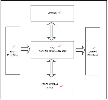
6.2  (6)
(6)
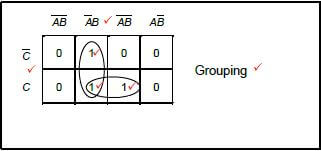
6.3 
![]() (8)
(8)
6.4
6.4.1 
6.4.2 Motor starting application. ✔ (1)
[40]
QUESTION 7: AMPLIFIERS
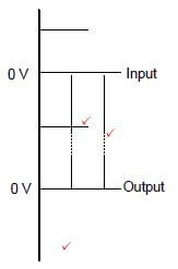
7.1  (5)
(5)
7.2
- Open loop voltage gain is infinite ✔
- Input impedance is Infinite✔
- Output impedance is zero ✔
- Infinite bandwidth (3)
7.3
- OP-amp circuits are placed in IC packages for protection ✔and for easy circuit use. ✔
- Op-amps are packaged as an integrated circuit in a hard plastic body with external pins for connections into circuits
(Accept any relevant answer (physical packaging, bubble wrap, etc.) (2)
7.4 Negative feedback occurs when a portion of the output signal in the op-amp circuit is feedback ✔to the input but 180° out of phase with the input ✔therefore subtracted from the input. ✔ (3)
7.5
- Reduces distortion and noise ✔
- Increases stability of the amplifier ✔
- Increases the bandwidth of the amplifier
- Output is predictable (2)
7.6

- Must show amplification✔
- Correct phase✔
- Inversion✔ (3)
7.7
7.7.1 
FIGURE: 7.2 (3)
7.7.2
AV = 1 + RF
RIN
= 1 + 12
3.3
= 4,64 ✔ (3)
7.7.3
VOUT = AV × VIN
= 4,64 × 6
= 27,84 V ✔ (3)
7.7.4 If RF is decreased, the gain of the op-amp will decrease ✔ as the gain is directly proportional to the value of the RF. ✔ (2)
7.8
7.8.1
FIGURE: 7.2 (6)
7.8.2 The capacitor acts as a timing device ✔ with the resistor which determines the rate at which the output voltage increases✔ determining the time it takes to reach saturation. ✔ (3)
7.9
7.9.1 They are used as audio frequency generators in audio amplifiers. ✔ Musical instruments✔, tone generator, GPS units. (2)
7.9.2
Fr = 1
2π √6RC
= 1
2π √6 × 12 × 103 × 260 × 10-9
= 20,82 Hz ✔ (3)
7.9.3 Sine wave shape ✔ (1)
7.9.4 Positive feedback ✔ (1)
7.10 The dual DC supply supplies energy✔ to the op amp to enable the op amp to amplify an input signal.✔ The dual DC supply sets the voltage parameters both positive and negative✔. (3)
7.11 Square Wave ✔ (1)
7.12
- Monitoring the rate of change in temperature of a furnace✔
- Square wave generator (1)
[50]
TOTAL: 200